HP 15-ba100 Maintenance and Service Guide - Page 62
Remove the two screw covers, If it is necessary to replace any of the display assembly subcomponents
 |
View all HP 15-ba100 manuals
Add to My Manuals
Save this manual to your list of manuals |
Page 62 highlights
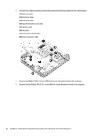
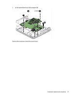
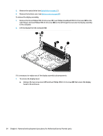
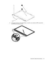
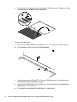
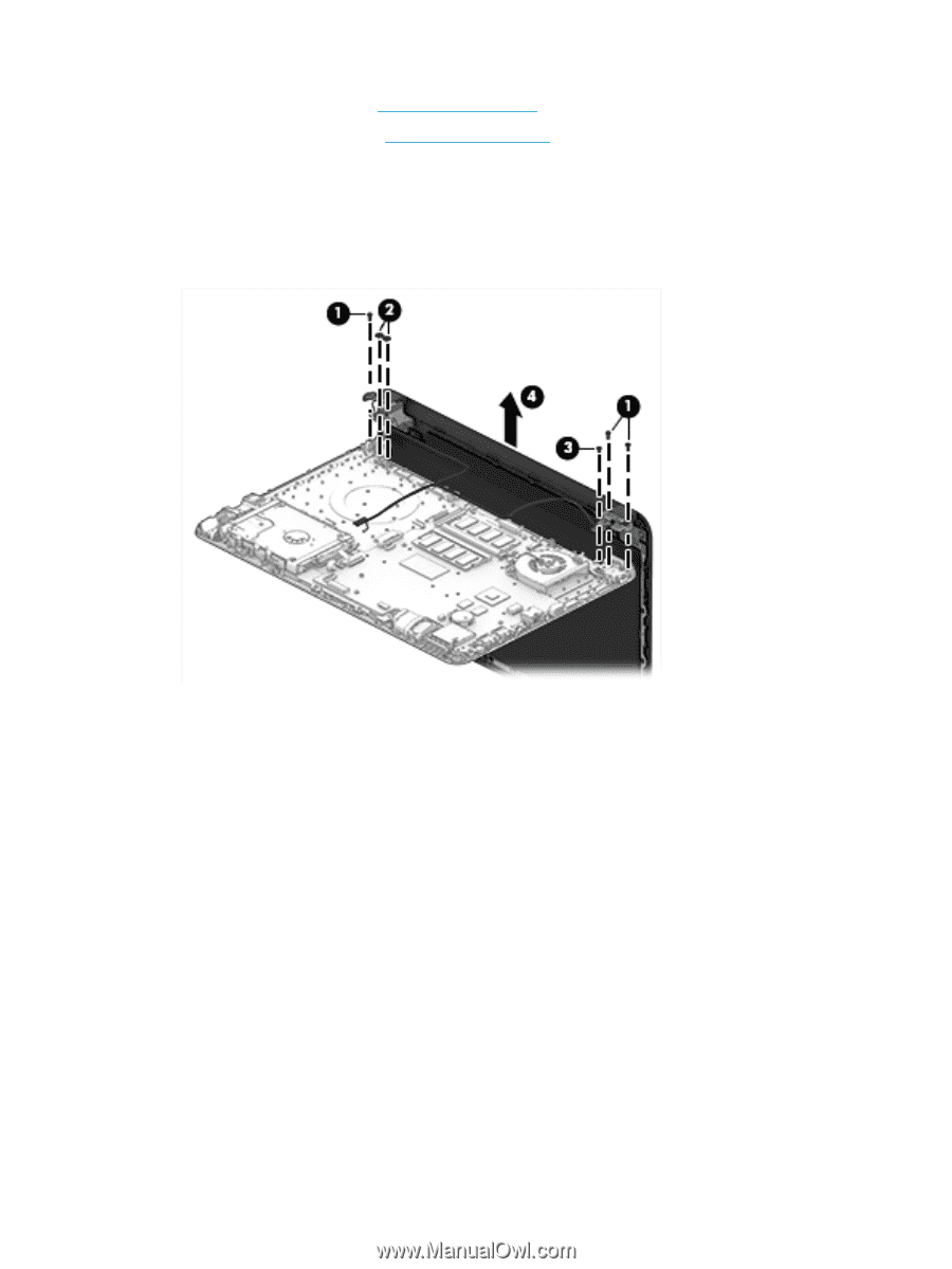
5. Remove the optical drive (see Optical drive on page 27). 6. Remove the bottom cover (see Bottom cover on page 30). To remove the display assembly: 1. Remove the three Phillips PM2.5×6.0 screws (1), two Phillips broadhead PM2.0×2.0 screws (2) (on the right hinge), and one Phillips PM2.5×4.0 screw (3) (on the left hinge) that secures the display assembly to the computer. 2. Lift the display from the computer (4). If it is necessary to replace any of the display assembly subcomponents: 1. To remove the display bezel: a. Remove the two screw covers (1) and two Phillips PM2.5×3.5 screws (2) that secure the display bezel to the enclosure. 54 Chapter 6 Removal and replacement procedures for Authorized Service Provider parts
-
 1
1 -
2
-
3
-
4
-
5
-
6
-
7
-
8
-
9
-
10
-
11
-
12
-
13
-
14
-
15
-
16
-
17
-
18
-
19
-
20
-
21
-
22
-
23
-
24
-
25
-
26
-
27
-
28
-
29
-
30
-
31
-
32
-
33
-
34
-
35
-
36
-
37
-
38
-
39
-
40
-
41
-
42
-
43
-
44
-
45
-
46
-
47
-
48
-
49
-
50
-
51
-
52
-
53
-
54
-
55
-
56
-
 57
57 -
 58
58 -
 59
59 -
 60
60 -
 61
61 -
 62
62 -
 63
63 -
 64
64 -
 65
65 -
 66
66 -
 67
67 -
68
-
69
-
70
-
71
-
72
-
73
-
74
-
75
-
76
-
77
-
78
-
79
-
80
-
81
-
82
-
83
-
84
-
85
-
86
-
87
-
88
-
89
-
90
-
91
-
92
-
93
-
94
-
95
-
96
-
97
-
98
-
99
-
100
-
101
-
102
 |
 |
5.
Remove the optical drive (see
Optical drive
on page
27
).
6.
Remove the bottom cover (see
Bottom cover
on page
30
).
To remove the display assembly:
1.
Remove the three Phillips PM2.5×6.0 screws
(1)
, two Phillips broadhead PM2.0×2.0 screws
(2)
(on the
right hinge), and one Phillips PM2.5×4.0 screw
(3)
(on the left hinge) that secures the display assembly
to the computer.
2.
Lift the display from the computer
(4)
.
If it is necessary to replace any of the display assembly subcomponents:
1.
To remove the display bezel:
a.
Remove the two screw covers
(1)
and two Phillips PM2.5×3.5 screws
(2)
that secure the display
bezel to the enclosure.
54
Chapter 6
Removal and replacement procedures for Authorized Service Provider parts