HP 15-bs000 Maintenance and Service Guide 1 - Page 119
display bezel, display assembly subcomponents
 |
View all HP 15-bs000 manuals
Add to My Manuals
Save this manual to your list of manuals |
Page 119 highlights
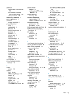
Index A AC adapter and battery light, identifying 8 action keys identifying 13 using 14 airplane mode key 14 antenna illustrated 24 antennas removing 79, 80 audio, product description 3 audio-out (headphone)/audio-in (microphone) combo jack, identifying 8 B backups 91 battery illustrated 21 removing 34 battery cover, identifying 15 battery lock, identifying 15 BIOS determining version 89 downloading an update 90 starting the Setup Utility 89 updating 89 Bluetooth label 16 boot order changing 95 bottom 16 bottom cover illustrated 21 removing 45 buttons left TouchPad 10 optical drive eject 7 power 12 right TouchPad 10 C cable locations removing 85 cables illustrated 25 cables, service considerations 29 camera identifying 9 camera light, identifying 9 camera/microphone cable illustrated 24 removing 41, 75, 76 camera/microphone module illustrated 23 removing 40, 74 caps lock light, identifying 11 components bottom 15 display 9 left side 8 right side 7 computer major components, illustrated 17 computer specifications 99 connector, power 8 connectors, service considerations 29 D display assembly illustrated 18 removing 72 display assembly subcomponents illustrated 23 removing 72 display bezel illustrated 23 removing 39, 73 display cable illustrated 24 removing 76 display enclosure illustrated 24 removing 81 display panel illustrated 23 product description 2 removing 41, 75, 76 display specifications 100 display subcomponents removal 39 spare part numbers 39 drive light, identifying 7 DVD±RW SuperMulti DL Drive specifications 103 E electrostatic discharge 30 eMMC module spare part number 18 equipment guidelines 32 esc key, identifying 13 Ethernet, product description 4 external media cards 4 external monitor port identifying 8 F fan illustrated 19 removing 62 fn key, identifying 13 G graphics, product description 2 grounding guidelines 30 guidelines equipment 32 grounding 30 packaging 31 transporting 31 workstation 31 H hard drive illustrated 19, 27 precautions 30 product description 3 removing 53 specifications 101 hard drive board illustrated 19 Index 111
-
 1
1 -
2
-
3
-
4
-
5
-
6
-
7
-
8
-
9
-
10
-
11
-
12
-
13
-
14
-
15
-
16
-
17
-
18
-
19
-
20
-
21
-
22
-
23
-
24
-
25
-
26
-
27
-
28
-
29
-
30
-
31
-
32
-
33
-
34
-
35
-
36
-
37
-
38
-
39
-
40
-
41
-
42
-
43
-
44
-
45
-
46
-
47
-
48
-
49
-
50
-
51
-
52
-
53
-
54
-
55
-
56
-
57
-
58
-
59
-
60
-
61
-
62
-
63
-
64
-
65
-
66
-
67
-
68
-
69
-
70
-
71
-
72
-
73
-
74
-
75
-
76
-
77
-
78
-
79
-
80
-
81
-
82
-
83
-
84
-
85
-
86
-
87
-
88
-
89
-
90
-
91
-
92
-
93
-
94
-
95
-
96
-
97
-
98
-
99
-
100
-
101
-
102
-
103
-
104
-
105
-
106
-
107
-
108
-
109
-
110
-
111
-
112
-
113
-
 114
114 -
 115
115 -
 116
116 -
 117
117 -
 118
118 -
 119
119 -
 120
120 -
 121
121 -
 122
122
 |
 |