HP 15-bs000 Maintenance and Service Guide 1 - Page 48
Disconnect the cable, from the module.
 |
View all HP 15-bs000 manuals
Add to My Manuals
Save this manual to your list of manuals |
Page 48 highlights
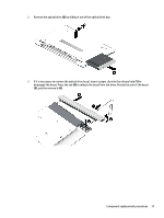
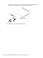
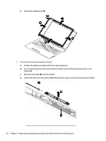
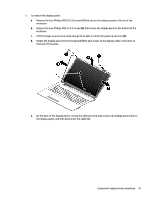
b. Remove the display bezel (4). 3. To remove the camera/microphone module: a. Position the display assembly with the top edge toward you. b. Pry up to disengage the camera/microphone module from the adhesive that secures it to the display (1). c. Disconnect the cable (2) from the module. d. Remove the tape from the enclosure (3). Replacement cameras come with tape already installed. 40 Chapter 6 Removal and replacement procedures for Authorized Service Provider parts
-
 1
1 -
2
-
3
-
4
-
5
-
6
-
7
-
8
-
9
-
10
-
11
-
12
-
13
-
14
-
15
-
16
-
17
-
18
-
19
-
20
-
21
-
22
-
23
-
24
-
25
-
26
-
27
-
28
-
29
-
30
-
31
-
32
-
33
-
34
-
35
-
36
-
37
-
38
-
39
-
40
-
41
-
42
-
 43
43 -
 44
44 -
 45
45 -
 46
46 -
 47
47 -
 48
48 -
 49
49 -
 50
50 -
 51
51 -
 52
52 -
 53
53 -
54
-
55
-
56
-
57
-
58
-
59
-
60
-
61
-
62
-
63
-
64
-
65
-
66
-
67
-
68
-
69
-
70
-
71
-
72
-
73
-
74
-
75
-
76
-
77
-
78
-
79
-
80
-
81
-
82
-
83
-
84
-
85
-
86
-
87
-
88
-
89
-
90
-
91
-
92
-
93
-
94
-
95
-
96
-
97
-
98
-
99
-
100
-
101
-
102
-
103
-
104
-
105
-
106
-
107
-
108
-
109
-
110
-
111
-
112
-
113
-
114
-
115
-
116
-
117
-
118
-
119
-
120
-
121
-
122
 |
 |
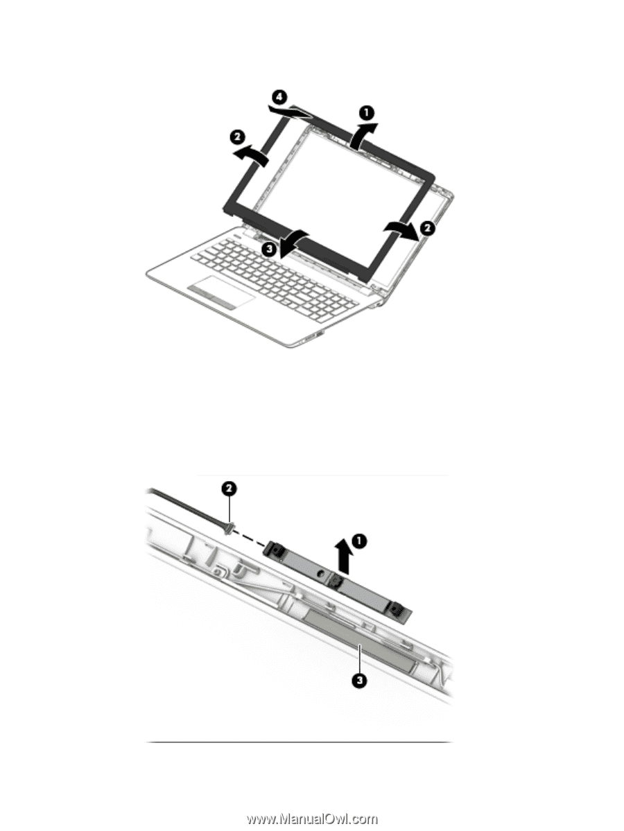
b.
Remove the display bezel
(4)
.
3.
To remove the camera/microphone module:
a.
Position the display assembly with the top edge toward you.
b.
Pry up to disengage the camera/microphone module from the adhesive that secures it to the
display
(1)
.
c.
Disconnect the cable
(2)
from the module.
d.
Remove the tape from the enclosure
(3)
. Replacement cameras come with tape already installed.
40
Chapter 6
Removal and replacement procedures for Authorized Service Provider parts