HP 15-bs000 Maintenance and Service Guide 1 - Page 79
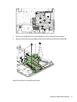
Reverse this procedure to install the system board., Rotate the side of the board upward
 |
View all HP 15-bs000 manuals
Add to My Manuals
Save this manual to your list of manuals |
Page 79 highlights
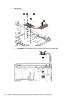
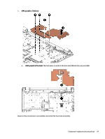
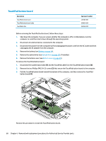
2. Remove the six Phillips PM2.0×3.0 screws (1) that secure the system board to the computer. 3. Rotate the side of the board upward (2), and then lift the system board out of the computer (3). Reverse this procedure to install the system board. Component replacement procedures 71
-
 1
1 -
2
-
3
-
4
-
5
-
6
-
7
-
8
-
9
-
10
-
11
-
12
-
13
-
14
-
15
-
16
-
17
-
18
-
19
-
20
-
21
-
22
-
23
-
24
-
25
-
26
-
27
-
28
-
29
-
30
-
31
-
32
-
33
-
34
-
35
-
36
-
37
-
38
-
39
-
40
-
41
-
42
-
43
-
44
-
45
-
46
-
47
-
48
-
49
-
50
-
51
-
52
-
53
-
54
-
55
-
56
-
57
-
58
-
59
-
60
-
61
-
62
-
63
-
64
-
65
-
66
-
67
-
68
-
69
-
70
-
71
-
72
-
73
-
 74
74 -
 75
75 -
 76
76 -
 77
77 -
 78
78 -
 79
79 -
 80
80 -
 81
81 -
 82
82 -
 83
83 -
 84
84 -
85
-
86
-
87
-
88
-
89
-
90
-
91
-
92
-
93
-
94
-
95
-
96
-
97
-
98
-
99
-
100
-
101
-
102
-
103
-
104
-
105
-
106
-
107
-
108
-
109
-
110
-
111
-
112
-
113
-
114
-
115
-
116
-
117
-
118
-
119
-
120
-
121
-
122
 |
 |
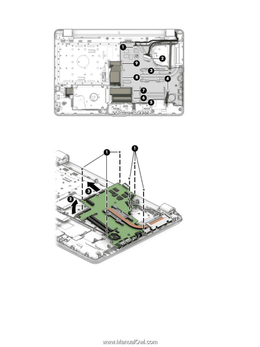
2.
Remove the six Phillips PM2.0×3.0 screws
(1)
that secure the system board to the computer.
3.
Rotate the side of the board upward
(2)
, and then lift the system board out of the computer
(3)
.
Reverse this procedure to install the system board.
Component replacement procedures
71