HP 15-bs000 Maintenance and Service Guide 1 - Page 60
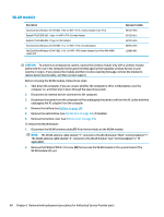
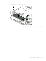
Optical drive connector board, Remove the Phillips PM2.0×2.0 screw
 |
View all HP 15-bs000 manuals
Add to My Manuals
Save this manual to your list of manuals |
Page 60 highlights
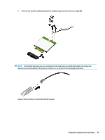
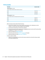
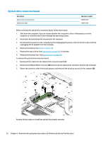
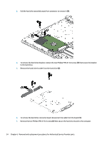
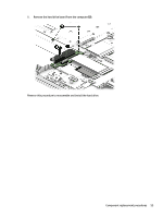
Optical drive connector board Description Optical drive connector board Optical drive cable Spare part number 924990-001 924926-001 Before removing the optical drive connector board, follow these steps: 1. Shut down the computer. If you are unsure whether the computer is off or in Hibernation, turn the computer on, and then shut it down through the operating system. 2. Disconnect all external devices connected to the computer. 3. Disconnect the power from the computer by first unplugging the power cord from the AC outlet and then unplugging the AC adapter from the computer. 4. Remove the battery (see Battery on page 34). 5. Remove the optical drive (see Optical drive on page 36), if installed. 6. Remove the bottom cover (see Bottom cover on page 45). To remove the optical drive connector board: 1. Disconnect the cable from the optical drive connector board (1). 2. Remove the Phillips PM2.0×2.0 screw (2) that secures the optical drive connector board to the computer. 3. Rotate the connector side of the board upward, and then pull the board up and out of the computer (3). Reverse this procedure to install the optical drive board connector. 52 Chapter 6 Removal and replacement procedures for Authorized Service Provider parts
-
 1
1 -
2
-
3
-
4
-
5
-
6
-
7
-
8
-
9
-
10
-
11
-
12
-
13
-
14
-
15
-
16
-
17
-
18
-
19
-
20
-
21
-
22
-
23
-
24
-
25
-
26
-
27
-
28
-
29
-
30
-
31
-
32
-
33
-
34
-
35
-
36
-
37
-
38
-
39
-
40
-
41
-
42
-
43
-
44
-
45
-
46
-
47
-
48
-
49
-
50
-
51
-
52
-
53
-
54
-
 55
55 -
 56
56 -
 57
57 -
 58
58 -
 59
59 -
 60
60 -
 61
61 -
 62
62 -
 63
63 -
 64
64 -
 65
65 -
66
-
67
-
68
-
69
-
70
-
71
-
72
-
73
-
74
-
75
-
76
-
77
-
78
-
79
-
80
-
81
-
82
-
83
-
84
-
85
-
86
-
87
-
88
-
89
-
90
-
91
-
92
-
93
-
94
-
95
-
96
-
97
-
98
-
99
-
100
-
101
-
102
-
103
-
104
-
105
-
106
-
107
-
108
-
109
-
110
-
111
-
112
-
113
-
114
-
115
-
116
-
117
-
118
-
119
-
120
-
121
-
122
 |
 |