HP 15-ra000 Maintenance and Service Guide 1 - Page 89
are available in Display Cover Support Kit.
 |
View all HP 15-ra000 manuals
Add to My Manuals
Save this manual to your list of manuals |
Page 89 highlights
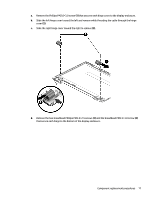
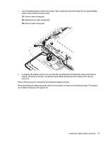
7. Use the following image to determine proper cable routing around the left hinge for the camera/display cable and the wireless antenna cables. (1): Camera cable routing path (2): Display/camera cable routing path (3): Antenna cable routing path 8. If replacing the display enclosure, be sure that the subcomponents (including the camera/microphone module, the antenna receivers, and all associated cables and hardware) are transferred to the new enclosure. Reverse this procedure to reassemble and install the display assembly. When assembling the display assemble, add the three washers as shown in the following image. The washers are available in Display Cover Support Kit. Component replacement procedures 81
-
 1
1 -
2
-
3
-
4
-
5
-
6
-
7
-
8
-
9
-
10
-
11
-
12
-
13
-
14
-
15
-
16
-
17
-
18
-
19
-
20
-
21
-
22
-
23
-
24
-
25
-
26
-
27
-
28
-
29
-
30
-
31
-
32
-
33
-
34
-
35
-
36
-
37
-
38
-
39
-
40
-
41
-
42
-
43
-
44
-
45
-
46
-
47
-
48
-
49
-
50
-
51
-
52
-
53
-
54
-
55
-
56
-
57
-
58
-
59
-
60
-
61
-
62
-
63
-
64
-
65
-
66
-
67
-
68
-
69
-
70
-
71
-
72
-
73
-
74
-
75
-
76
-
77
-
78
-
79
-
80
-
81
-
82
-
83
-
 84
84 -
 85
85 -
 86
86 -
 87
87 -
 88
88 -
 89
89 -
 90
90 -
 91
91 -
 92
92 -
 93
93 -
 94
94 -
95
-
96
-
97
-
98
-
99
-
100
-
101
-
102
-
103
-
104
-
105
-
106
-
107
-
108
-
109
-
110
-
111
-
112
-
113
-
114
-
115
-
116
-
117
-
118
-
119
-
120
-
121
-
122
 |
 |
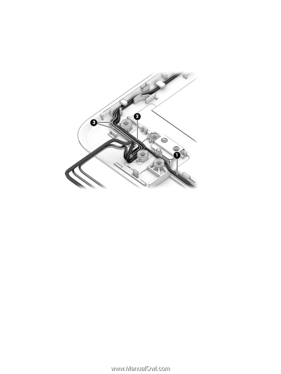
7.
Use the following image to determine proper cable routing around the left hinge for the camera/display
cable and the wireless antenna cables.
(1)
: Camera cable routing path
(2)
: Display/camera cable routing path
(3)
: Antenna cable routing path
8.
If replacing the display enclosure, be sure that the subcomponents (including the camera/microphone
module, the antenna receivers, and all associated cables and hardware) are transferred to the new
enclosure.
Reverse this procedure to reassemble and install the display assembly.
When assembling the display assemble, add the three washers as shown in the following image. The washers
are available in Display Cover Support Kit.
Component replacement procedures
81