HP 2000-379WM HP 2000 Notebook PC - Maintenance and Service Guide - Page 49
Remove the Phillips PM2.5×6.0 screw, module compartment cover is available in the Plastics Kit
 |
View all HP 2000-379WM manuals
Add to My Manuals
Save this manual to your list of manuals |
Page 49 highlights
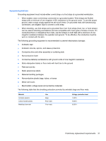
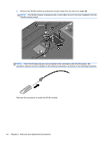
3. Disconnect the power from the computer by first unplugging the power cord from the AC outlet and then unplugging the AC adapter from the computer. 4. Remove the battery (see Battery on page 39). Remove the optical drive: 1. Loosen the captive screw (1) that secures the memory module/wireless module compartment cover to the computer. 2. Lift the rear edge of the memory module/wireless module compartment cover (2) up and forward until it rests at an angle. 3. Remove the memory module/wireless module compartment cover. The memory module/wireless module compartment cover is available in the Plastics Kit, spare part number 646131-001. 4. Remove the Phillips PM2.5×6.0 screw (1) that secures the optical drive to the computer. 5. Insert an unbent paper clip or similar thin tool into the optical drive tab access (2) to release the optical drive tray from the optical drive. Component replacement procedures 41
-
 1
1 -
2
-
3
-
4
-
5
-
6
-
7
-
8
-
9
-
10
-
11
-
12
-
13
-
14
-
15
-
16
-
17
-
18
-
19
-
20
-
21
-
22
-
23
-
24
-
25
-
26
-
27
-
28
-
29
-
30
-
31
-
32
-
33
-
34
-
35
-
36
-
37
-
38
-
39
-
40
-
41
-
42
-
43
-
 44
44 -
 45
45 -
 46
46 -
 47
47 -
 48
48 -
 49
49 -
 50
50 -
 51
51 -
 52
52 -
 53
53 -
 54
54 -
55
-
56
-
57
-
58
-
59
-
60
-
61
-
62
-
63
-
64
-
65
-
66
-
67
-
68
-
69
-
70
-
71
-
72
-
73
-
74
-
75
-
76
-
77
-
78
-
79
-
80
-
81
-
82
-
83
-
84
-
85
-
86
-
87
-
88
-
89
-
90
-
91
-
92
-
93
-
94
-
95
-
96
-
97
-
98
-
99
-
100
-
101
-
102
-
103
-
104
-
105
-
106
-
107
-
108
-
109
-
110
-
111
-
112
-
113
-
114
-
115
 |
 |
