HP 2000-379WM HP 2000 Notebook PC - Maintenance and Service Guide - Page 71
built into the base enclosure., Release the wireless antenna cables from the clips
 |
View all HP 2000-379WM manuals
Add to My Manuals
Save this manual to your list of manuals |
Page 71 highlights
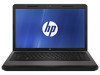
3. Disconnect the power from the computer by first unplugging the power cord from the AC outlet and then unplugging the AC adapter from the computer. 4. Remove the battery (see Battery on page 39), and then remove the following components: ● Optical drive (see Optical drive (select models only) on page 40) ● WLAN module (see WLAN module on page 43) ● Keyboard (see Keyboard on page 49) ● Top cover (see Top cover on page 51) ● USB board (see USB board on page 58) ● Power connector cable (see Power connector cable on page 59) Remove the display assembly: 1. Disconnect the display panel cable (1) from the system board. 2. Release the wireless antenna cables from the clips (2) built into the base enclosure. CAUTION: Support the display assembly when removing the following screws. Failure to support the display assembly can result in damage to the display assembly and other computer components. 3. Remove the four Phillips PM2.5×6.0 screws (3) that secure the display assembly to the computer. 4. Remove the display assembly (4). Component replacement procedures 63
-
 1
1 -
2
-
3
-
4
-
5
-
6
-
7
-
8
-
9
-
10
-
11
-
12
-
13
-
14
-
15
-
16
-
17
-
18
-
19
-
20
-
21
-
22
-
23
-
24
-
25
-
26
-
27
-
28
-
29
-
30
-
31
-
32
-
33
-
34
-
35
-
36
-
37
-
38
-
39
-
40
-
41
-
42
-
43
-
44
-
45
-
46
-
47
-
48
-
49
-
50
-
51
-
52
-
53
-
54
-
55
-
56
-
57
-
58
-
59
-
60
-
61
-
62
-
63
-
64
-
65
-
 66
66 -
 67
67 -
 68
68 -
 69
69 -
 70
70 -
 71
71 -
 72
72 -
 73
73 -
 74
74 -
 75
75 -
 76
76 -
77
-
78
-
79
-
80
-
81
-
82
-
83
-
84
-
85
-
86
-
87
-
88
-
89
-
90
-
91
-
92
-
93
-
94
-
95
-
96
-
97
-
98
-
99
-
100
-
101
-
102
-
103
-
104
-
105
-
106
-
107
-
108
-
109
-
110
-
111
-
112
-
113
-
114
-
115
 |
 |