HP 2300 Service Manual - Page 149
Formatter, Remove five screws callout 3.
 |
UPC - 808736470698
View all HP 2300 manuals
Add to My Manuals
Save this manual to your list of manuals |
Page 149 highlights
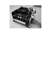
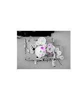
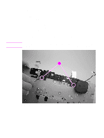
Formatter 1 Remove the following covers and assemblies: • I/O cover (see page 113) • DIMM cover (page 115) • rear cover (page 116) • front cover (page 119) • control panel (page 120) • top cover assembly (page 121) 2 Use a flatblade screwdriver to press down the tab at the top of one connector (callout 1) and then unplug the connector. 3 Unplug the flat, flexible cable (callout 2) from the formatter. 4 Remove five screws (callout 3). 2 32 12 Figure 72. Removing the formatter 5 Lift the formatter off of the printer. Reinstall note Use the locator pin at the lower edge of the formatter plate (toward the back of the printer) to place the plate correctly. ENWW Chapter 6 Removal and replacement 147
-
 1
1 -
2
-
3
-
4
-
5
-
6
-
7
-
8
-
9
-
10
-
11
-
12
-
13
-
14
-
15
-
16
-
17
-
18
-
19
-
20
-
21
-
22
-
23
-
24
-
25
-
26
-
27
-
28
-
29
-
30
-
31
-
32
-
33
-
34
-
35
-
36
-
37
-
38
-
39
-
40
-
41
-
42
-
43
-
44
-
45
-
46
-
47
-
48
-
49
-
50
-
51
-
52
-
53
-
54
-
55
-
56
-
57
-
58
-
59
-
60
-
61
-
62
-
63
-
64
-
65
-
66
-
67
-
68
-
69
-
70
-
71
-
72
-
73
-
74
-
75
-
76
-
77
-
78
-
79
-
80
-
81
-
82
-
83
-
84
-
85
-
86
-
87
-
88
-
89
-
90
-
91
-
92
-
93
-
94
-
95
-
96
-
97
-
98
-
99
-
100
-
101
-
102
-
103
-
104
-
105
-
106
-
107
-
108
-
109
-
110
-
111
-
112
-
113
-
114
-
115
-
116
-
117
-
118
-
119
-
120
-
121
-
122
-
123
-
124
-
125
-
126
-
127
-
128
-
129
-
130
-
131
-
132
-
133
-
134
-
135
-
136
-
137
-
138
-
139
-
140
-
141
-
142
-
143
-
 144
144 -
 145
145 -
 146
146 -
 147
147 -
 148
148 -
 149
149 -
 150
150 -
 151
151 -
 152
152 -
 153
153 -
 154
154 -
155
-
156
-
157
-
158
-
159
-
160
-
161
-
162
-
163
-
164
-
165
-
166
-
167
-
168
-
169
-
170
-
171
-
172
-
173
-
174
-
175
-
176
-
177
-
178
-
179
-
180
-
181
-
182
-
183
-
184
-
185
-
186
-
187
-
188
-
189
-
190
-
191
-
192
-
193
-
194
-
195
-
196
-
197
-
198
-
199
-
200
-
201
-
202
-
203
-
204
-
205
-
206
-
207
-
208
-
209
-
210
-
211
-
212
-
213
-
214
-
215
-
216
-
217
-
218
-
219
-
220
-
221
-
222
-
223
-
224
-
225
-
226
-
227
-
228
-
229
-
230
-
231
-
232
-
233
-
234
-
235
-
236
-
237
-
238
-
239
-
240
-
241
-
242
-
243
-
244
-
245
-
246
-
247
-
248
-
249
-
250
-
251
-
252
-
253
-
254
-
255
-
256
-
257
-
258
-
259
-
260
-
261
-
262
-
263
-
264
-
265
-
266
-
267
-
268
-
269
-
270
-
271
-
272
-
273
-
274
-
275
-
276
-
277
-
278
-
279
-
280
-
281
-
282
-
283
-
284
-
285
-
286
-
287
-
288
-
289
-
290
-
291
-
292
-
293
-
294
-
295
-
296
 |
 |

ENWW
Chapter 6 Removal and replacement
147
Formatter
1
Remove the following covers and assemblies:
•
I/O cover (see page 113)
•
DIMM cover (page 115)
•
rear cover (page 116)
•
front cover (page 119)
•
control panel (page 120)
•
top cover assembly (page 121)
2
Use a flatblade screwdriver to press down the tab at the top of one connector (callout 1) and
then unplug the connector.
3
Unplug the flat, flexible cable (callout 2) from the formatter.
4
Remove five screws (callout 3).
Figure 72.
Removing the formatter
5
Lift the formatter off of the printer.
Reinstall note
Use the locator pin at the lower edge of the formatter plate (toward the back of the printer) to
place the plate correctly.
2
2
2
2
1
3