HP 4320t HP 4320t Mobile Thin Client - Maintenance and Service Guide - Page 70
Display assembly, Battery, on Switch cover, Keyboard, Speakers, Palm rest, WLAN module
 |
View all HP 4320t manuals
Add to My Manuals
Save this manual to your list of manuals |
Page 70 highlights
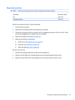
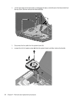
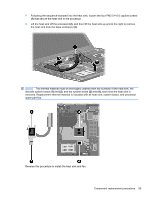
Display assembly NOTE: The display assembly spare part kit includes 2 WLAN antennas and cables. Description Display assembly, 33.8-cm (13.3-in) HD (1366x768 resolution) ● Display bezel ● Display panel (available separately in APJ, using part number 623175-001) ● Display Hinge Kit (includes display hinges and left and right panel brackets) ● Display cable and microphone ● WLAN antennas and cables (included with display assembly) ● Display back cover (includes 2 WLAN antennas and cables and 1 microphone) Spare part number 599553-001 599532-001 599536-001 605557-001 599526-001 Before removing the display assembly, follow these steps: 1. Shut down the computer. 2. Disconnect all external devices connected to the computer. 3. Disconnect the power from the computer by first unplugging the power cord from the AC outlet and then unplugging the AC adapter from the computer. 4. Remove the battery (see Battery on page 36). 5. Remove the following components: a. Switch cover (see Switch cover on page 37) b. Keyboard (see Keyboard on page 39) c. Speakers (see Speakers on page 46) d. Palm rest (see Palm rest on page 48) e. WLAN cables (see WLAN module on page 54) Remove the display assembly: CAUTION: Support the display assembly when removing the following screws. Failure to support the display assembly can result in damage to the display assembly and other computer components. 1. Disconnect the display cable from the system board (1), and remove all cables from the routing channels along the top cover (2). 2. Remove the five T8 M2.5x6.0 screws and one PM 2.5x5.0 screw (3) that secure the display assembly to the base enclosure. 62 Chapter 4 Removal and replacement procedures
-
 1
1 -
2
-
3
-
4
-
5
-
6
-
7
-
8
-
9
-
10
-
11
-
12
-
13
-
14
-
15
-
16
-
17
-
18
-
19
-
20
-
21
-
22
-
23
-
24
-
25
-
26
-
27
-
28
-
29
-
30
-
31
-
32
-
33
-
34
-
35
-
36
-
37
-
38
-
39
-
40
-
41
-
42
-
43
-
44
-
45
-
46
-
47
-
48
-
49
-
50
-
51
-
52
-
53
-
54
-
55
-
56
-
57
-
58
-
59
-
60
-
61
-
62
-
63
-
64
-
 65
65 -
 66
66 -
 67
67 -
 68
68 -
 69
69 -
 70
70 -
 71
71 -
 72
72 -
 73
73 -
 74
74 -
 75
75 -
76
-
77
-
78
-
79
-
80
-
81
-
82
-
83
-
84
-
85
-
86
-
87
-
88
-
89
-
90
-
91
-
92
-
93
-
94
-
95
-
96
-
97
-
98
-
99
-
100
-
101
-
102
-
103
-
104
-
105
-
106
-
107
-
108
 |
 |
