HP 5.7kVA 208 Volt L21-20 3-Phase Input 18xC13/3xNEMA HP Monitored Power Distr - Page 26
Connecting Optional Environmental Monitoring Probe Equipment
 |
View all HP 5.7kVA 208 Volt L21-20 3-Phase Input 18xC13/3xNEMA manuals
Add to My Manuals
Save this manual to your list of manuals |
Page 26 highlights
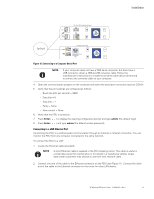
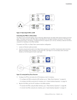
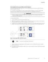
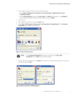
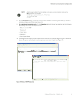
Installation Connecting Optional Environmental Monitoring Probe Equipment You can purchase optional EMP equipment to monitor temperature and humidity around the PDU and to monitor the status of sensors. You can install an optional EMP now or after completing the PDU installation and startup. Optional EMP equipment can be installed without turning off power to the PDU or the devices connected to it. ! IMPORTANT Follow all installation and operation safety information provided in the manufacturer's instruction manual for the EMP equipment. To install an optional EMP: 1. Locate the EMP and the RJ-45-to-RJ-45 Ethernet cable. 2. Refer to the manufacturer's installation manual for instructions to connect the external contact inputs to the optional EMP for the external contact devices you plan to monitor. 3. Locate the Ethernet cable dedicated to the EMP. Connect one end of the cable to the RJ-45 connector on the EMP, then connect the other end of the cable to the RJ-45 connector on the PDU (see Figure 13). 22U, 36U, 42U Model Front Panel 1U Model Front Panel Figure 13. Connecting the EMP to the RS-232 Connector NOTE The maximum cable length is 2.99m (9.8 ft). 4. Use the mounting method appropriate to your installation to mount the EMP in a convenient location anywhere on the rack. 5. Use cable ties to secure the Ethernet cable out of the way as needed. On startup, the PDU automatically recognizes the EMP. HP Monitored PDU User's Guide P-164000281-Rev 1 20
-
 1
1 -
2
-
3
-
4
-
5
-
6
-
7
-
8
-
9
-
10
-
11
-
12
-
13
-
14
-
15
-
16
-
17
-
18
-
19
-
20
-
 21
21 -
 22
22 -
 23
23 -
 24
24 -
 25
25 -
 26
26 -
 27
27 -
 28
28 -
 29
29 -
 30
30 -
 31
31 -
32
-
33
-
34
-
35
-
36
-
37
-
38
-
39
-
40
-
41
-
42
-
43
-
44
-
45
-
46
-
47
-
48
-
49
-
50
-
51
-
52
-
53
-
54
-
55
-
56
-
57
-
58
-
59
-
60
-
61
-
62
-
63
-
64
-
65
-
66
-
67
-
68
-
69
-
70
-
71
-
72
-
73
-
74
-
75
-
76
-
77
-
78
-
79
-
80
-
81
-
82
-
83
-
84
-
85
-
86
-
87
-
88
-
89
-
90
-
91
-
92
-
93
-
94
-
95
-
96
-
97
-
98
-
99
-
100
-
101
-
102
-
103
-
104
-
105
-
106
-
107
-
108
-
109
-
110
-
111
-
112
-
113
-
114
-
115
-
116
-
117
-
118
-
119
-
120
 |
 |
