HP 5.7kVA 208 Volt L21-20 3-Phase Input 18xC13/3xNEMA HP Monitored Power Distr - Page 35
Ph Configurations, Pin Positions, Operation Overview
 |
View all HP 5.7kVA 208 Volt L21-20 3-Phase Input 18xC13/3xNEMA manuals
Add to My Manuals
Save this manual to your list of manuals |
Page 35 highlights
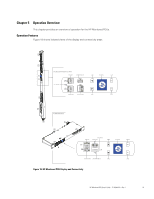
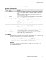
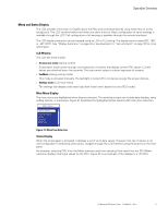
Operation Overview Table 3 describes the operation features shown in Figure 18. Table 3. Display and Connectivity Features Reference Number Feature Description 1 LCD Window LCD Window: Displays information about load status, events, measurements, identification, and settings. The LCD also provides some basic configuration. For more information, see "Menu and Status Display" on page 31. Navigation buttons: Navigate through the display. For more information, see "Front Panel Ports, Status Indicators, and Operation Buttons" on page 32. 2 Reset opening Restarts the PDU communications module. Resetting the PDU does not affect the loads. Insert and retract a probe in the reset opening to perform a communications module restart. 3 Connectivity and Monitoring ports Serial Service and Communication Port: Connects to the serial (COM) connector on a computer with a DB9-to-RJ-45 cable, allowing the computer to act as a configuration console. As an alternative, the connection can be used to connect an optional EMP in order to collect temperature and humidity data. Ethernet Port Connector: Connects to a LAN, allowing configuration through a 10/100 autosensing network connection. 4 Circuit breakers 5 Power outlets 6 Input power cord Daisy Chain Port Connector: Used to daisy-chain two PDUs together. USB Port: Reserved for future use. Activate if the load current rating of a power outlet exceeds 16A (Europe) / 20A (US). Power to the outlet turns off automatically. To reset the circuit breaker, turn the breaker from off to on. NOTE The On/Off positions are indicated on the circuit breakers. NOTE To manually disconnect power to a device that is connected to the PDU, disconnect the device's power cord from the PDU power outlet. Allows you to connect one device to each outlet. The outlets are grouped by phase. Group configurations cannot be changed. For more information, see "Outlets and Circuit Breakers" on page 30. Allows you to connect to the power source. Input power cords are permanent for most models. Only the D9N45A and D9N46A models have detachable input power cords. 3Ph Configurations The type of PDU input connector plug varies to accommodate different amperage ratings for 3Ph models. The IEC 60309 connector plugs are configured as delta or wye topologies as follows: l The delta configuration uses a four-wire input connector plug with three phase wires, a protective earth (ground) wire, and no neutral wire. This is commonly expressed as 3W+PE (delta). l The wye configuration uses a five-wire input connector plug with three phase wires, a protective earth (ground) wire, and a neutral wire. This is commonly expressed as 3W+N+PE (wye). Pin Positions The pin arrays are different for four-wire (delta) and five-wire (wye) 3Ph configurations. See Figure 19 for example delta and wye pin positions. HP Monitored PDU User's Guide P-164000281-Rev 1 29
-
 1
1 -
2
-
3
-
4
-
5
-
6
-
7
-
8
-
9
-
10
-
11
-
12
-
13
-
14
-
15
-
16
-
17
-
18
-
19
-
20
-
21
-
22
-
23
-
24
-
25
-
26
-
27
-
28
-
29
-
 30
30 -
 31
31 -
 32
32 -
 33
33 -
 34
34 -
 35
35 -
 36
36 -
 37
37 -
 38
38 -
 39
39 -
 40
40 -
41
-
42
-
43
-
44
-
45
-
46
-
47
-
48
-
49
-
50
-
51
-
52
-
53
-
54
-
55
-
56
-
57
-
58
-
59
-
60
-
61
-
62
-
63
-
64
-
65
-
66
-
67
-
68
-
69
-
70
-
71
-
72
-
73
-
74
-
75
-
76
-
77
-
78
-
79
-
80
-
81
-
82
-
83
-
84
-
85
-
86
-
87
-
88
-
89
-
90
-
91
-
92
-
93
-
94
-
95
-
96
-
97
-
98
-
99
-
100
-
101
-
102
-
103
-
104
-
105
-
106
-
107
-
108
-
109
-
110
-
111
-
112
-
113
-
114
-
115
-
116
-
117
-
118
-
119
-
120
 |
 |
