HP 60 HP StorageWorks 60 Modular Smart Array Enclosure Maintenance and Service - Page 31
Backplane
 |
View all HP 60 manuals
Add to My Manuals
Save this manual to your list of manuals |
Page 31 highlights
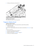
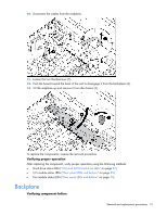
10. Disconnect the cables from the midplane. 11. Loosen the two thumbscrews (1). 12. Push the board toward the back of the unit to disengage it from the backplane (2). 13. Tilt the midplane up and remove it from the chassis (3). To replace the components, reverse the removal procedure. Verifying proper operation After replacing the component, verify proper operation using the following methods: • Hard drive status LEDs ("SAS and SATA hard drive LEDs" on page 37) • I/O module status LEDs ("Rear panel LEDs and buttons" on page 35) • Fan module status LEDs ("Rear panel LEDs and buttons" on page 35) Backplane Verifying component failure Removal and replacement procedures 31
-
 1
1 -
2
-
3
-
4
-
5
-
6
-
7
-
8
-
9
-
10
-
11
-
12
-
13
-
14
-
15
-
16
-
17
-
18
-
19
-
20
-
21
-
22
-
23
-
24
-
25
-
 26
26 -
 27
27 -
 28
28 -
 29
29 -
 30
30 -
 31
31 -
 32
32 -
 33
33 -
 34
34 -
 35
35 -
 36
36 -
37
-
38
-
39
-
40
-
41
-
42
 |
 |

Removal and replacement procedures
31
10.
Disconnect the cables from the midplane.
11.
Loosen the two thumbscrews (1).
12.
Push the board toward the back of the unit to disengage it from the backplane (2).
13.
Tilt the midplane up and remove it from the chassis (3).
To replace the components, reverse the removal procedure.
Verifying proper operation
After replacing the component, verify proper operation using the following methods:
•
Hard drive status LEDs ("
SAS and SATA hard drive LEDs
" on page
37
)
•
I/O module status LEDs ("
Rear panel LEDs and buttons
" on page
35
)
•
Fan module status LEDs ("
Rear panel LEDs and buttons
" on page
35
)
Backplane
Verifying component failure