HP 9000 Superdome SX2000 Generic Site Preparation Guide - Edition 6 - Page 15
Equipment Grounding Implementation Details, System Installation Guidelines
 |
View all HP 9000 Superdome SX2000 manuals
Add to My Manuals
Save this manual to your list of manuals |
Page 15 highlights
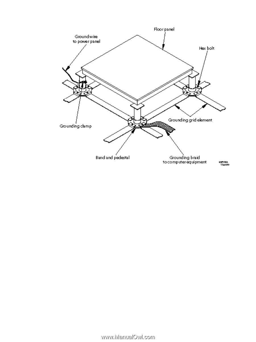
Figure 1-1 Raised Floor Metal Strip Ground System Equipment Grounding Implementation Details Connect all HP equipment cabinets to the site ground grid as follows: 1. Check that the braid contact connection points are free of paint or other insulating material and treated with a contact enhancement compound (similar to Burndy Penetrox). 2. Check that the braid contact on each end of the ground strap consists of a terminal and connection hardware (a 1/4-inch (6.0-mm) bolt, nuts, and washers). 3. Attach one end of each ground strap to the applicable cabinet ground lug. 4. Attach the other end to the nearest pedestal base (raised floor) or cable trough ground point (nonraised floor). 5. After achieving a safe and effective 50-60Hz grounding system and a safe and effective SRG, then consider cabinet-to-floor grounding. HP does not require this step. System Installation Guidelines This section contains information about installation practices and highlights some common installation hazards. It addresses both power and data communications cable installations, and highlights installation. Electrical Factors 15
-
 1
1 -
2
-
3
-
4
-
5
-
6
-
7
-
8
-
9
-
 10
10 -
 11
11 -
 12
12 -
 13
13 -
 14
14 -
 15
15 -
 16
16 -
 17
17 -
 18
18 -
 19
19 -
 20
20 -
21
-
22
-
23
-
24
-
25
-
26
-
27
-
28
-
29
-
30
-
31
-
32
-
33
-
34
-
35
-
36
-
37
-
38
-
39
-
40
-
41
-
42
-
43
-
44
-
45
-
46
 |
 |