HP 9000 Superdome SX2000 Generic Site Preparation Guide - Edition 6 - Page 28
Storage and Powered Off, Floor Plan Grid
 |
View all HP 9000 Superdome SX2000 manuals
Add to My Manuals
Save this manual to your list of manuals |
Page 28 highlights
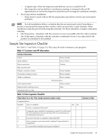
1 The maximum elevation for all operating environmental classes is 3,050 m (10,007 ft). 2 Dry bulb temperature is the regular ambient temperature. Derate maximum dry bulb temperature 1 ºC/300 m (34 ºF/984 ft) above 900 m (2,953 ft). 3 Must be noncondensing environment. 4 Controlled computer room environment is comparable to ASHRAE Class 1 and IEC 60721 Class 3K1. 5 Local product groups must make business decisions for the appropriate values. With installed media, the minimum temperature is 10 °C (50 °F) and maximum relative humidity is limited to 80%. Specific media requirements may vary. Include the possible addition of equipment or other changes in space requirements to the space plan and create an equipment layout plan which contains provisions for the following: • Channels or fixtures used for routing data cables and power cables • Access to air-conditioning ducts, filters, lighting, and electrical power hardware • Power conditioning equipment • Cabinets for cleaning materials • Maintenance area and spare parts Storage and Powered Off See Table 1-6 (page 28) for storage and powered off conditions. The information described in the following table provides typical temperature and relative humidity ranges for HP equipment that are subjected to the following environmental conditions: • Removed from the original shipping container and installed in the typical environment • In transit shipment or in storage (in shipping material or container) See Table 1-5 (page 27) for the environmental values to operating equipment. Table 1-6 Typical Range of Product Power-Off Storage and Shipping Environments Type of Product Storage Temp °C, dry bulb [regular ambient temp.] (°F) Relative Dew Point Humidity %: (max) Noncondensing Powered-Off (installed) Temp °C, dry bulb [regular ambient temp.] (°F) Relative Dew Point Humidity %: (max) Noncondensing All Classes -40 to 80 10 to 90 32 (-40 to 176) 5 to 45 10 to 90 29 (41 to 113) Special (or Contract) See the contract or industry requirements. NOTE: The values shown in Table 1-6 (page 28) meet or exceed all ASHRAE specifications. Floor Plan Grid Use a floor plan grid designing the location of equipment in the computer room. Also use the floor plan grid when arranging the locations of the following items: • Air-conditioning vents • Lighting fixtures • Utility outlets • Access areas for power wiring and air-conditioning filters 28 General Site Preparation Guidelines
-
 1
1 -
2
-
3
-
4
-
5
-
6
-
7
-
8
-
9
-
10
-
11
-
12
-
13
-
14
-
15
-
16
-
17
-
18
-
19
-
20
-
21
-
22
-
 23
23 -
 24
24 -
 25
25 -
 26
26 -
 27
27 -
 28
28 -
 29
29 -
 30
30 -
 31
31 -
 32
32 -
 33
33 -
34
-
35
-
36
-
37
-
38
-
39
-
40
-
41
-
42
-
43
-
44
-
45
-
46
 |
 |