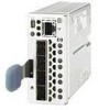
HP A7533A HP StorageWorks Fabric OS 5.X Procedures User Guide (AA-RVHWB-TE, Se - Page 92
Obtaining slot information, Field, Value
 |
UPC - 829160830858
View all HP A7533A manuals
Add to My Manuals
Save this manual to your list of manuals |
Page 92 highlights
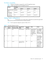
Table 17 Supported configuration options (continued) Option 4 Number of Maximum number Supported port domains of ports per switch blades 2 64/64 Left side: FC-16 Right side: FC2-16 Supported CP blades CP2 5 1 256 FC4-16, FC4-32 CP4 Notes Results N/A Two 64-port switches (Blade ID 2 on slots 1-4; ID 4 on slots 7-10. Blade ID 5 on slots 5, 6) CP4 fits all chassis except the D2 chassis. Option 5 is the default configuration option for 4/256 SAN Director. One 256-port switch (Blade IDs 4, 17, and 18 on slots 1-4, 7-10. Blade ID 16 on slots 5, 6) The following sections contain procedures for obtaining chassis information and for configuring director domains using the chassisConfig command. Obtaining slot information For a Core Switch 2/64 or SAN Director 2/128 configured as two logical switches, the chassis-wide commands display or control both logical switches. In the default configuration, the SAN Director 2/128 and 4/256 SAN Director are configured as one logical switch, so the chassis-wide commands display and control the single logical switch. Displaying the status of all slots in the chassis 1. Connect to the switch and log in as user or admin. 2. Issue the slotShow command to display the current status of each slot in the system. The format of the display includes a header and four fields for each slot. The fields and their possible values are: Field Slot Blade Type ID Value Displays the physical slot number. Displays the blade type: • SW BLADE: The blade is a switch. • CP BLADE: The blade is a CP. • UNKNOWN: The blade is not present or its type is not recognized. Displays the hardware ID of the blade type. 92 Configuring Core Switch 2/64, SAN Director 2/128, and 4/256 SAN Director
-
 1
1 -
2
-
3
-
4
-
5
-
6
-
7
-
8
-
9
-
10
-
11
-
12
-
13
-
14
-
15
-
16
-
17
-
18
-
19
-
20
-
21
-
22
-
23
-
24
-
25
-
26
-
27
-
28
-
29
-
30
-
31
-
32
-
33
-
34
-
35
-
36
-
37
-
38
-
39
-
40
-
41
-
42
-
43
-
44
-
45
-
46
-
47
-
48
-
49
-
50
-
51
-
52
-
53
-
54
-
55
-
56
-
57
-
58
-
59
-
60
-
61
-
62
-
63
-
64
-
65
-
66
-
67
-
68
-
69
-
70
-
71
-
72
-
73
-
74
-
75
-
76
-
77
-
78
-
79
-
80
-
81
-
82
-
83
-
84
-
85
-
86
-
 87
87 -
 88
88 -
 89
89 -
 90
90 -
 91
91 -
 92
92 -
 93
93 -
 94
94 -
 95
95 -
 96
96 -
 97
97 -
98
-
99
-
100
-
101
-
102
-
103
-
104
-
105
-
106
-
107
-
108
-
109
-
110
-
111
-
112
-
113
-
114
-
115
-
116
-
117
-
118
-
119
-
120
-
121
-
122
-
123
-
124
-
125
-
126
-
127
-
128
-
129
-
130
-
131
-
132
-
133
-
134
-
135
-
136
-
137
-
138
-
139
-
140
-
141
-
142
-
143
-
144
-
145
-
146
-
147
-
148
-
149
-
150
-
151
-
152
-
153
-
154
-
155
-
156
-
157
-
158
-
159
-
160
-
161
-
162
-
163
-
164
-
165
-
166
-
167
-
168
-
169
-
170
-
171
-
172
-
173
-
174
-
175
-
176
-
177
-
178
-
179
-
180
-
181
-
182
-
183
-
184
-
185
-
186
-
187
-
188
-
189
-
190
-
191
-
192
-
193
-
194
-
195
-
196
-
197
-
198
-
199
-
200
-
201
-
202
-
203
-
204
-
205
-
206
-
207
-
208
-
209
-
210
-
211
-
212
-
213
-
214
-
215
-
216
-
217
-
218
-
219
-
220
-
221
-
222
-
223
-
224
-
225
-
226
-
227
-
228
-
229
-
230
-
231
-
232
-
233
-
234
-
235
-
236
-
237
-
238
-
239
-
240
-
241
-
242
-
243
-
244
-
245
-
246
-
247
-
248
 |
 |
