HP BLc7000 HP Direct-Connect External SAS Storage for HP BladeSystem Solutions - Page 80
Troubleshooting the HP 3Gb SAS BL Switch, Troubleshooting the MDS600 storage enclosure
 |
View all HP BLc7000 manuals
Add to My Manuals
Save this manual to your list of manuals |
Page 80 highlights
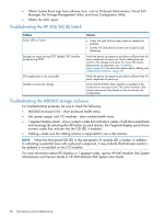
• Obtain System Event Logs from software tools, such as Onboard Administrator, Virtual SAS Manager, the Storage Management Utility, and Array Configuration Utility. • Obtain the ADU report. Troubleshooting the HP 3Gb SAS BL Switch Problem Amber LED on Switch Storage not ready during POST (blade) OR Controller lockup during POST VSM application is not accessible Unable to access the storage Solution • Check OA and VSM for status alerts to identify the problem. • See the HP 3Gb SAS BL Switch User Guide for LED definitions. Verify the power up sequence and allow sufficient time for each component to power up. Verify cabling from the switch to the storage enclosures. For more information about power-up sequence, see "Installation steps" (page 60). For more information about cabling, see "Deployment examples" (page 92). Verify the power up sequence and allow sufficient time for each component to power up. Verify that the P700m SAS controller is installed in the correct server mezzanine slot. The switch must be in the correct interconnect bay based on the mezzanine slot configuration. Troubleshooting the MDS600 storage enclosure For troubleshooting purposes, be sure to check the following: • MDS600 enclosure LEDs-show enclosure health status. • Fan, power supply, and I/O modules-show module health status. • 7-segment display panel-shows numeric codes that indicate a variety of self-discovered faults and warnings. By selecting the UID button on each drawer, the 7-segment display panel shows numeric codes that indicate why the GSI LED is enabled. • Cabling-make sure the cabling scheme is supported for use in this solution. NOTE: When the front-panel GSI LED or the rear-panel I/O module LED is Amber, in addition to indicating a potential issue with a physical component, it may indicate that firmware needs to be updated or re-installed on the I/O modules. For more information about LED displays or 7-segment codes, see the HP 600 Modular Disk System Maintenance and Service Guide or HP 600 Modular Disk System User Guide. 80 Maintenance and troubleshooting
-
 1
1 -
2
-
3
-
4
-
5
-
6
-
7
-
8
-
9
-
10
-
11
-
12
-
13
-
14
-
15
-
16
-
17
-
18
-
19
-
20
-
21
-
22
-
23
-
24
-
25
-
26
-
27
-
28
-
29
-
30
-
31
-
32
-
33
-
34
-
35
-
36
-
37
-
38
-
39
-
40
-
41
-
42
-
43
-
44
-
45
-
46
-
47
-
48
-
49
-
50
-
51
-
52
-
53
-
54
-
55
-
56
-
57
-
58
-
59
-
60
-
61
-
62
-
63
-
64
-
65
-
66
-
67
-
68
-
69
-
70
-
71
-
72
-
73
-
74
-
 75
75 -
 76
76 -
 77
77 -
 78
78 -
 79
79 -
 80
80 -
 81
81 -
 82
82 -
 83
83 -
 84
84 -
 85
85 -
86
-
87
-
88
-
89
-
90
-
91
-
92
-
93
-
94
-
95
-
96
-
97
-
98
-
99
-
100
-
101
-
102
-
103
-
104
-
105
-
106
-
107
-
108
-
109
-
110
-
111
-
112
-
113
-
114
-
115
-
116
-
117
-
118
-
119
-
120
-
121
-
122
-
123
 |
 |
