HP Brio 71xx hp brio 71xx, self-repair instructions - Page 3
Task 5 Replacing the Floppy Disk, Drive, Task 6 Replacing the DIMMs, Task 7 Replacing the Power
 |
View all HP Brio 71xx manuals
Add to My Manuals
Save this manual to your list of manuals |
Page 3 highlights
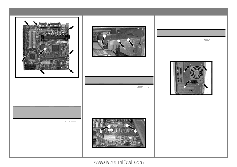
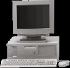
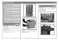
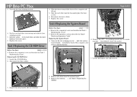
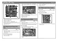
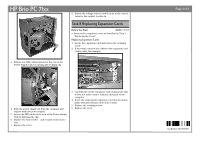
HP Brio PC 71xx ‡‡ Page 3 of 4 3. Remove the two retaining screws ƒ, and slide the 4. Replace the DIMM, pushing it home until the retaining floppy disk tray towards the rear of the computer, then clips ‚ lock it in place. ‡ out. 5. Replace the cover. ‡ ‡ ‡ ‡ ‡ 6. Replace the system board. 7. Replace the eight screws ‡. 8. Replace the memory „ and processor …. 9. Refit the cables into their appropriate sockets. 10. Slide the system board chassis back into the computer and replace the screws ‚. 11. Replace the cover. Task 5 Replacing the Floppy Disk Drive ‚ ƒƒ 4. Unscrew the floppy disk from its tray. 5. Replace the Floppy Disk Drive, and screw it to its tray. 6. Slide the tray back into place. 7. Refit the two cables ‚. 8. Replace the cover. Task 7 Replacing the Power Supply Before You Start T-15 & + • Remove the computer's cover as described in in Task 1 "Replacing the Cover" Replacing the Power Supply 1. Locate and remove the four screws ‚ on the back of the computer. ‚ ‚ Task 6 Replacing the DIMMs Before You Start T-15 • Remove the computer's cover as described in Task 1 "Replacing the Cover". • Rest the system board chassis in the horizontal position as described in Task 4 "Replacing the System Board". Replacing the DIMMs 1. Locate the DIMMs on your system board. 2. Press out the two retaining clips ‚ at either end of the DIMM (this releases the DIMM). ‚ ‚ 2. Disconnect all of the white connectors ƒ on the system board and drives. Before You Start T-15 • Remove the computer's cover as described in Task 1 "Replacing the Cover" • Remove the hard disk as described in Task 2 "Replacing the Hard Disk" Replacing the Floppy Disk Drive 1. Locate the Floppy Disk drive. 2. Remove the cables ‚. ‚ ‚ 3. Holding the DIMM by its edges, lift it clear of the socket.
-
 1
1 -
 2
2 -
 3
3 -
 4
4
 |
 |