HP Brio 83xx hp brio 83xx, online reference guide - Page 49
CPU SPEED, CPUCLK, Ratio, Jumper Position
 |
View all HP Brio 83xx manuals
Add to My Manuals
Save this manual to your list of manuals |
Page 49 highlights
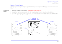
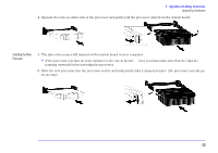
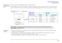
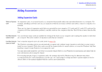
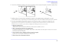
3 Upgrading and Adding Accessories Upgrading Hardware Setting the System Set the system board configuration jumpers (or jumper block). Board for the Processor Type The following diagram shows the location on the system board of the jumpers used to configure the computer for the new processor. If you are in any doubt as to whether you should change jumper settings or not, contact your reseller. CPU Clock Ratio (J23): System Board Fan Chassis Connector Sample configuration jumper setting for a 233 MHz processor (if no jumper block is used) 19 J23 2 10 CPUCLK 233 MHz 266 MHz 300 MHz 333 MHz CPU SPEED Ratio Jumper Position 2 / 7 1-2 and 9-10 1 / 4 5-6, 7-8 and 9-10 2 / 9 5-6 and 9-10 1 / 5 7-8 and 9-10 Completing the Installation Note If your computer is supplied with a jumper block, you will need to change this with individual jumpers when you upgrade the processor. 1 Replace the airflow guide covering the processor. Verify that the Fan cable is still connected to the Fan Chassis Connector on the system board. 2 Install any other accessories before returning the computer to the upright position, replacing the cover, and reconnecting the power cords and any telecommunications cables. 3 Turn on the display and computer. The computer should recognize the new processor. 49
-
 1
1 -
2
-
3
-
4
-
5
-
6
-
7
-
8
-
9
-
10
-
11
-
12
-
13
-
14
-
15
-
16
-
17
-
18
-
19
-
20
-
21
-
22
-
23
-
24
-
25
-
26
-
27
-
28
-
29
-
30
-
31
-
32
-
33
-
34
-
35
-
36
-
37
-
38
-
39
-
40
-
41
-
42
-
43
-
 44
44 -
 45
45 -
 46
46 -
 47
47 -
 48
48 -
 49
49 -
 50
50 -
 51
51 -
 52
52 -
 53
53 -
 54
54 -
55
-
56
-
57
-
58
-
59
-
60
-
61
-
62
-
63
-
64
-
65
-
66
-
67
-
68
-
69
-
70
-
71
-
72
-
73
-
74
-
75
-
76
-
77
-
78
-
79
-
80
-
81
-
82
-
83
-
84
-
85
-
86
 |
 |
