HP Brocade 8/12c Brocade Network Advisor SMI Agent Developer's Guide - Page 91
Fibre Channel Router data model, Translate, Domain, Front Domain
 |
View all HP Brocade 8/12c manuals
Add to My Manuals
Save this manual to your list of manuals |
Page 91 highlights
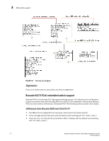
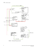
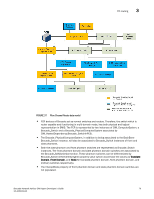
FC routing 3 FIGURE 37 Fibre Channel Router data model • FCR devices of Brocade act as normal switches and routers. Therefore, the switch which is router capable and functioning in multi-domain mode, has both physical and logical representation in SMIS. The FCR is represented by two instances of CIM_ComputerSystem, a Brocade_Switch and a Brocade_PhysicalComputerSystem associated by CIM_HostedDependency(Brocade_SwitchInPCS). • The Brocade_PhysicalComputerSystem, in addition to being associated to the BackBone Brocade_Switch instance, will also be associated to Brocade_Switch instances of front and xlate phantoms. • Both the xlate phantom and front phantom switches are represented as Brocade_Switch instances. The front phantom domain and xlate phantom domain switches are associated by the Brocade_SANActiveConnection. These phantom switches can be differentiated by Brocade_Switch.OtherIdentifyingInfo property value (which would have the values as Translate Domain, Front Domain, and None for translate phantom domain, front phantom domain, and ordinary switches respectively). • The InteropMode property of front phantom domain and xlate phantom domain switches are not populated. Brocade Network Advisor SMI Agent Developer's Guide 79 53-1002169-01
-
 1
1 -
2
-
3
-
4
-
5
-
6
-
7
-
8
-
9
-
10
-
11
-
12
-
13
-
14
-
15
-
16
-
17
-
18
-
19
-
20
-
21
-
22
-
23
-
24
-
25
-
26
-
27
-
28
-
29
-
30
-
31
-
32
-
33
-
34
-
35
-
36
-
37
-
38
-
39
-
40
-
41
-
42
-
43
-
44
-
45
-
46
-
47
-
48
-
49
-
50
-
51
-
52
-
53
-
54
-
55
-
56
-
57
-
58
-
59
-
60
-
61
-
62
-
63
-
64
-
65
-
66
-
67
-
68
-
69
-
70
-
71
-
72
-
73
-
74
-
75
-
76
-
77
-
78
-
79
-
80
-
81
-
82
-
83
-
84
-
85
-
 86
86 -
 87
87 -
 88
88 -
 89
89 -
 90
90 -
 91
91 -
 92
92 -
 93
93 -
 94
94 -
 95
95 -
 96
96 -
97
-
98
-
99
-
100
-
101
-
102
-
103
-
104
-
105
-
106
-
107
-
108
-
109
-
110
-
111
-
112
-
113
-
114
-
115
-
116
-
117
-
118
-
119
-
120
-
121
-
122
-
123
-
124
-
125
-
126
-
127
-
128
-
129
-
130
-
131
-
132
-
133
-
134
-
135
-
136
-
137
-
138
-
139
-
140
-
141
-
142
-
143
-
144
-
145
-
146
-
147
-
148
-
149
-
150
-
151
-
152
-
153
-
154
-
155
-
156
-
157
-
158
-
159
-
160
-
161
-
162
-
163
-
164
-
165
-
166
-
167
-
168
 |
 |
