HP Cc3310 UserÆs Guide and Technical UserÆs Guide - HP Carri - Page 20
Internal Chassis Features
 |
View all HP Cc3310 manuals
Add to My Manuals
Save this manual to your list of manuals |
Page 20 highlights
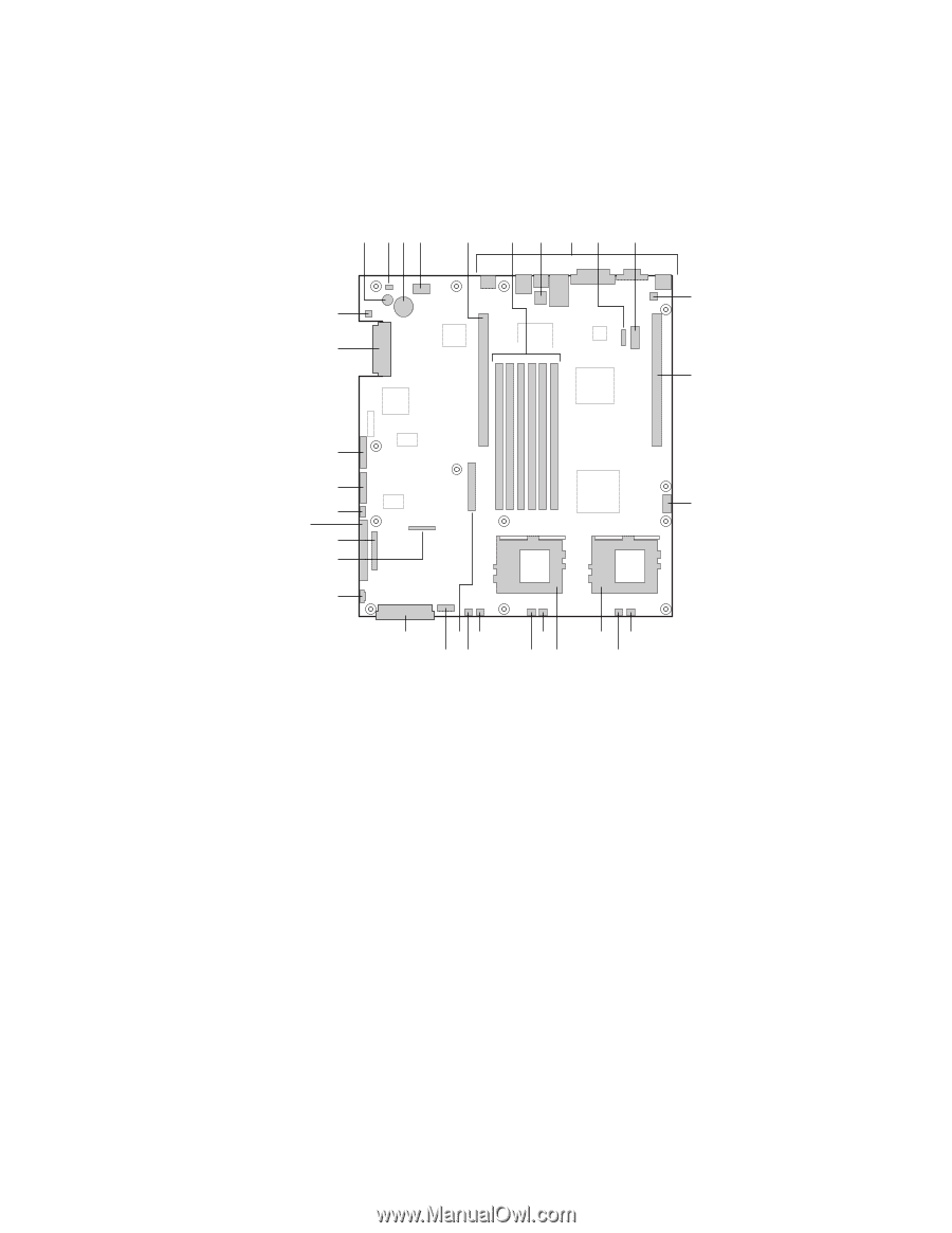
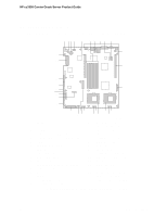
HP cc3300 Carrier Grade Server Product Guide Internal Chassis Features Figure 5 shows the location of the server board's connectors and other components. A BC D E FG HI J K GG FF L EE DD CC M BB AA Z Y X VT WU R SQ PN O OM12815 A Speaker B ID LED C Battery D Diagnostic LEDs (POST code) E 66 MHz/64-bit PCI riser slot (full height) F DIMM slots G DCD/DSR jumper block H I/O ports I ICMB connector J COM 1 serial header K Chassis intrusion connector L 66 MHz/64-bit PCI riser slot (low profile) M USB 3 & 4 header N Sys fan 3 connector O CPU 2 fan connector P Secondary processor socket Q Primary processor socket R Sys fan 2 connector S CPU 1 fan connector T Sys fan 1 connector U Aux fan connector V Floppy drive connector W Fan module connector X Main power connector Y Auxiliary signal connector Z Floppy/FP/IDE connector AA Alternate front panel connector BB ATA/IDE connector CC IPMB connector DD SSI front panel connector EE Configuration jumper block FF SCSI connector (SCSI version only) GG Hard Disk Drive LED header Figure 5. Server Board Connector and Component Locations 20 Chassis Description
-
 1
1 -
2
-
3
-
4
-
5
-
6
-
7
-
8
-
9
-
10
-
11
-
12
-
13
-
14
-
 15
15 -
 16
16 -
 17
17 -
 18
18 -
 19
19 -
 20
20 -
 21
21 -
 22
22 -
 23
23 -
 24
24 -
 25
25 -
26
-
27
-
28
-
29
-
30
-
31
-
32
-
33
-
34
-
35
-
36
-
37
-
38
-
39
-
40
-
41
-
42
-
43
-
44
-
45
-
46
-
47
-
48
-
49
-
50
-
51
-
52
-
53
-
54
-
55
-
56
-
57
-
58
-
59
-
60
-
61
-
62
-
63
-
64
-
65
-
66
-
67
-
68
-
69
-
70
-
71
-
72
-
73
-
74
-
75
-
76
-
77
-
78
-
79
-
80
-
81
-
82
-
83
-
84
-
85
-
86
-
87
-
88
-
89
-
90
-
91
-
92
-
93
-
94
-
95
-
96
-
97
-
98
-
99
-
100
-
101
-
102
-
103
-
104
-
105
-
106
-
107
-
108
-
109
-
110
-
111
-
112
-
113
-
114
-
115
-
116
-
117
-
118
-
119
-
120
-
121
-
122
-
123
-
124
-
125
-
126
-
127
-
128
-
129
-
130
-
131
-
132
-
133
 |
 |