HP Cc3310 UserÆs Guide and Technical UserÆs Guide - HP Carri - Page 80
Installing or Removing a Terminator
 |
View all HP Cc3310 manuals
Add to My Manuals
Save this manual to your list of manuals |
Page 80 highlights
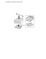
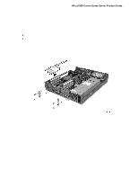
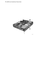
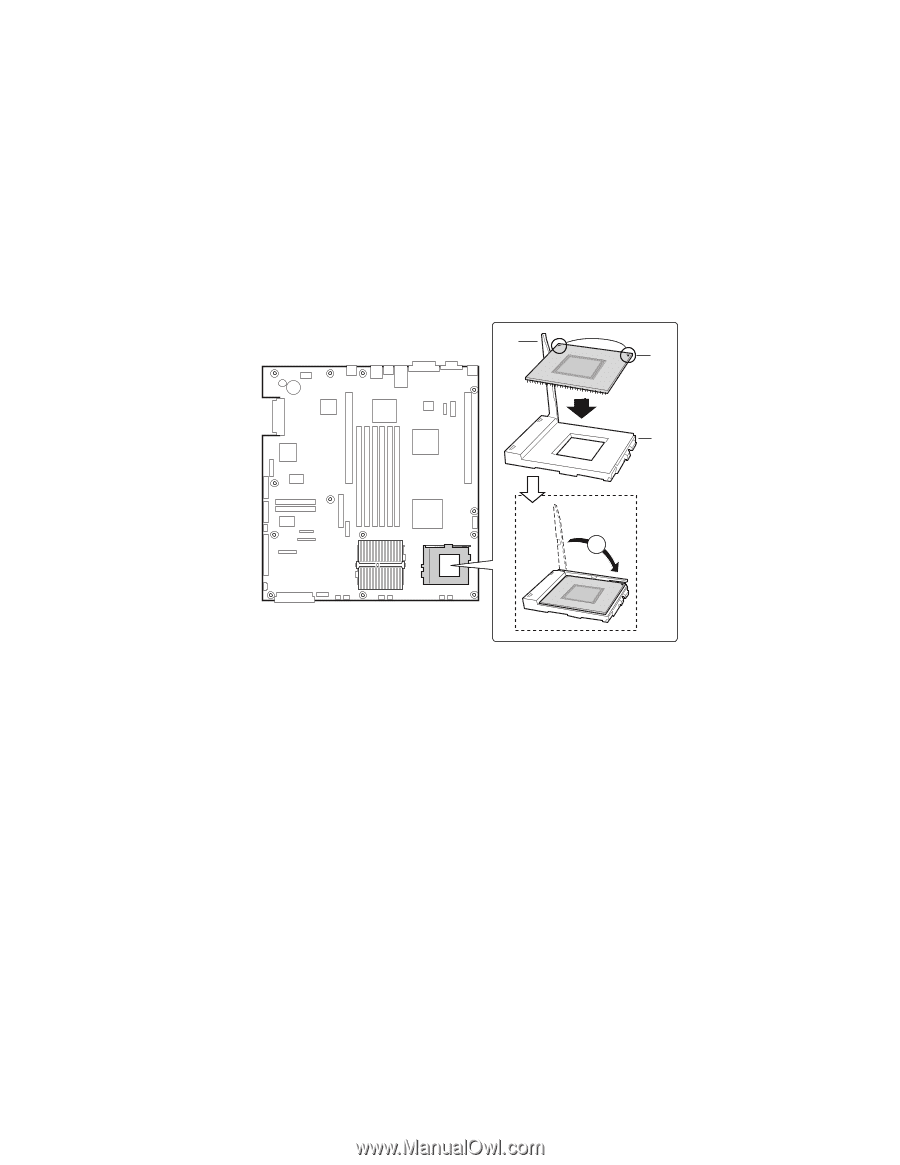
HP cc3300 Carrier Grade Server Product Guide Installing or Removing a Terminator 1. Observe the safety and ESD precautions at the beginning of this chapter and the additional cautions given here. 2. Raise the locking bar (B in Figure 22) on the socket (A in Figure 22). 3. Align the corner marks on the terminator (C in Figure 22) along the locking bar side of the processor socket. 4. Place the terminator into the socket. 5. Lower the locking bar (D in Figure 22) until it latches to the side of the processor socket. 6. Perform these steps in reverse to remove the terminator. B C A D Figure 22. Installing a Terminator OM11787 80 Upgrading the Hardware
-
 1
1 -
2
-
3
-
4
-
5
-
6
-
7
-
8
-
9
-
10
-
11
-
12
-
13
-
14
-
15
-
16
-
17
-
18
-
19
-
20
-
21
-
22
-
23
-
24
-
25
-
26
-
27
-
28
-
29
-
30
-
31
-
32
-
33
-
34
-
35
-
36
-
37
-
38
-
39
-
40
-
41
-
42
-
43
-
44
-
45
-
46
-
47
-
48
-
49
-
50
-
51
-
52
-
53
-
54
-
55
-
56
-
57
-
58
-
59
-
60
-
61
-
62
-
63
-
64
-
65
-
66
-
67
-
68
-
69
-
70
-
71
-
72
-
73
-
74
-
 75
75 -
 76
76 -
 77
77 -
 78
78 -
 79
79 -
 80
80 -
 81
81 -
 82
82 -
 83
83 -
 84
84 -
 85
85 -
86
-
87
-
88
-
89
-
90
-
91
-
92
-
93
-
94
-
95
-
96
-
97
-
98
-
99
-
100
-
101
-
102
-
103
-
104
-
105
-
106
-
107
-
108
-
109
-
110
-
111
-
112
-
113
-
114
-
115
-
116
-
117
-
118
-
119
-
120
-
121
-
122
-
123
-
124
-
125
-
126
-
127
-
128
-
129
-
130
-
131
-
132
-
133
 |
 |
HP cc3300 Carrier Grade Server Product Guide
80
Upgrading the Hardware
Installing or Removing a Terminator
1.
Observe the safety and ESD precautions at the beginning of this chapter and the additional
cautions given here.
2.
Raise the locking bar (B in Figure 22) on the socket (A in Figure 22).
3.
Align the corner marks on the terminator (C in Figure 22) along the locking bar side of the
processor socket.
4.
Place the terminator into the socket.
5.
Lower the locking bar (D in Figure 22) until it latches to the side of the processor socket.
6.
Perform these steps in reverse to remove the terminator.
OM11787
A
B
D
C
Figure 22.
Installing a Terminator