HP Cc3310 Processor Installation and Replacement Procedure For the HP cc3310 C - Page 3
B, Installing Processors, C, Lowering the Locking Bar
 |
View all HP Cc3310 manuals
Add to My Manuals
Save this manual to your list of manuals |
Page 3 highlights
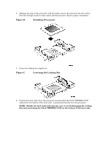
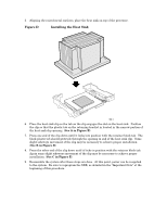
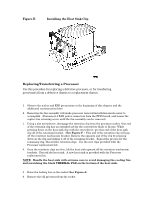
2. Aligning the pins of the processor with the socket, insert the processor into the socket. Note the triangle locator on the socket and the processor chip for proper orientation. Figure B Installing Processors 3. Lower the locking bar completely. Figure C Lowering the Locking Bar 4. Position the heat sink above the processor ensuring that the black THERMAL PAD (adhered to the bottom of the heat sink) is positioned directly over the processor. NOTE: Handle the heat sink with extreme care to avoid damaging the cooling fins and scratching the black THERMAL PAD on the bottom of the heat sink.
-
 1
1 -
 2
2 -
 3
3 -
 4
4 -
 5
5 -
 6
6
 |
 |

2.
Aligning the pins of the processor with the socket, insert the processor into the socket.
Note the triangle locator on the socket and the processor chip for proper orientation.
Figure B
Installing Processors
3.
Lower the locking bar completely.
Figure C
Lowering the Locking Bar
4.
Position the heat sink above the processor ensuring that the black THERMAL PAD
(adhered to the bottom of the heat sink)
is positioned directly over the processor.
NOTE
:
Handle the heat sink with extreme care to avoid damaging the cooling
fins and scratching the black THERMAL PAD on the bottom of the heat sink.