HP Cc3310 Processor Installation and Replacement Procedure For the HP cc3310 C - Page 4
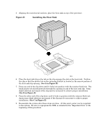
D, Installing the Heat Sink
 |
View all HP Cc3310 manuals
Add to My Manuals
Save this manual to your list of manuals |
Page 4 highlights
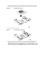
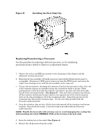
5. Aligning the raised metal surfaces, place the heat sink on top of the processor. Figure D Installing the Heat Sink 6. Place the heat sink clip so the tab on the clip engages the slot on the heat sink. Position the clip so that the plastic tab on the retaining bracket in located in the narrow portion of the heat sink clip opening. (See A in Figure E) 7. Press one end of the clip down until it locks into position with the retainer block tab. The black plastic tab should protrude through the opening in end of the heat sink clip. Some slight sideways movement of the clip may be necessary to achieve proper installation. (See B in Figure E) 8. Press the other end of the clip down until it locks in position with the retainer block tab. Again some slight sideways movement of the clip may be necessary to achieve proper installation. (See C in Figure E) 9. Reassemble the system after these steps are done. At this point, power can be reapplied to the system. Be sure to reprogram the SDR, as detailed in the "Important Note" at the beginning of this procedure.
-
 1
1 -
 2
2 -
 3
3 -
 4
4 -
 5
5 -
 6
6
 |
 |
