HP Chromebook 14 G3 Chromebook model numbers 14- x000 through 14-x099 Maintena - Page 38
Connector board, Detach the connector board cable
 |
View all HP Chromebook 14 G3 manuals
Add to My Manuals
Save this manual to your list of manuals |
Page 38 highlights
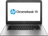
Connector board NOTE: The connector board spare part kit includes a cable and double-sided adhesive. Description For use only on computer models equipped with WWAN capability (includes SD Card Reader slot and SIM slot) For use only on computer models not equipped with WWAN capability (includes SD Card Reader slot) Spare part number 787715-001 787714-001 Before removing the connector board, follow these steps: 1. Turn off the computer. If you are unsure whether the computer is off or in Hibernation, turn the computer on, and then shut it down through the operating system. 2. Disconnect the power from the computer by unplugging the power cord from the computer. 3. Disconnect all external devices from the computer. 4. Remove the keyboard/top cover (see Keyboard/top cover on page 23). Remove the connector board: 1. Release the ZIF connector (1) to which the connector board ribbon cable is attached, and then disconnect the connector board ribbon cable from the system board. 2. Detach the connector board cable (2) from the battery. (The connector board cable is attached to the battery with double-sided adhesive.) 3. Remove the two Philllips PM1.9×2.4 broad head screws (3) that secure the connector board to the base enclosure. 32 Chapter 5 Removal and replacement procedures
-
 1
1 -
2
-
3
-
4
-
5
-
6
-
7
-
8
-
9
-
10
-
11
-
12
-
13
-
14
-
15
-
16
-
17
-
18
-
19
-
20
-
21
-
22
-
23
-
24
-
25
-
26
-
27
-
28
-
29
-
30
-
31
-
32
-
 33
33 -
 34
34 -
 35
35 -
 36
36 -
 37
37 -
 38
38 -
 39
39 -
 40
40 -
 41
41 -
 42
42 -
 43
43 -
44
-
45
-
46
-
47
-
48
-
49
-
50
-
51
-
52
-
53
-
54
-
55
-
56
-
57
-
58
-
59
-
60
-
61
 |
 |
