HP Cluster Platform Hardware Kits v2010 HP ProCurve 2610 Series Rail Kit Insta - Page 10
Installation Preparations, Bracket Orientation
 |
View all HP Cluster Platform Hardware Kits v2010 manuals
Add to My Manuals
Save this manual to your list of manuals |
Page 10 highlights
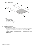
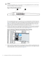
Figure 1-3 Bracket Orientation 4 1 4 2 6 3 5 Figure 1-3 shows the following components and their orientation to the HP ProCurve 2610 Series switch. 1. Left mounting bracket. 2. Right mounting bracket. 3. The ProCurve 2610 series switch. 4. Support bracket mounting position. See Figure 2-1 for more information on where and how to mount the support bracket. 5. M6 screws. 6. M4 screws. 1.8 Installation Preparations Prepare for the installation as follows: 1. Ensure that the cluster is shut down and powered off so that you can perform the installation. 2. Prepare a suitable work surface, such as a table, on which you can safely arrange the unpacked parts and have room to attach the rail brackets to the HP ProCurve 2610 Series switch. 3. Unpack the HP ProCurve 2610 Series switch and lay it on a flat, level surface with its ports facing toward you. 10 Preparing for Installation
-
 1
1 -
2
-
3
-
4
-
 5
5 -
 6
6 -
 7
7 -
 8
8 -
 9
9 -
 10
10 -
 11
11 -
 12
12 -
 13
13 -
 14
14 -
 15
15 -
16
-
17
-
18
 |
 |
