HP Cluster Platform Hardware Kits v2010 HP ProCurve 2610 Series Rail Kit Insta - Page 12
Caution, Attach the Mounting Brackets
 |
View all HP Cluster Platform Hardware Kits v2010 manuals
Add to My Manuals
Save this manual to your list of manuals |
Page 12 highlights
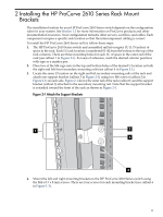
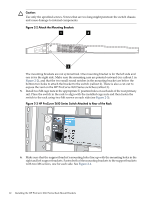
Caution: Use only the specified screws. Screws that are too long might penetrate the switch chassis and cause damage to internal components. Figure 2-2 Attach the Mounting Brackets 1 3 2 The mounting brackets are not symmetrical. One mounting bracket is for the left side and one is for the right side. Make sure the mounting ears are pointed outward (see callout 1 in Figure 2-2), and that the two small round notches in the mounting bracket are below the bottom two holes to attach the bracket to the switch (callout 2). There is also a cut-out to expose the vent on the HP ProCurve 2610 Series switches (callout 3). 5. Install two M6 cage nuts in the appropriate U position holes on each side of the rear primary rail. Place the switch in the rack to align with the installed cage nuts and then fasten the switch to the rack using two M6 screws on each side (see Figure 2-3). Figure 2-3 HP ProCurve 2610 Series Switch Attached to Rear of the Rack Power Fault Locator Console ProCurve Switch 2610-24 Status RPS Act FDx Test Spd Reset Clear Off=10 Mbps. 6. Make sure that the support bracket's mounting holes line up with the mounting holes in the right and left support brackets. Fasten both of the mounting brackets to the support brackets with two M6 screws, one for each side. See Figure 2-4. 12 Installing the HP ProCurve 2610 Series Rack Mount Brackets
-
 1
1 -
2
-
3
-
4
-
5
-
6
-
 7
7 -
 8
8 -
 9
9 -
 10
10 -
 11
11 -
 12
12 -
 13
13 -
 14
14 -
 15
15 -
 16
16 -
 17
17 -
18
 |
 |
