HP Cluster Platform Hardware Kits v2010 Integrity rx2600 Cable Management Tray - Page 4
Orienting the Components
 |
View all HP Cluster Platform Hardware Kits v2010 manuals
Add to My Manuals
Save this manual to your list of manuals |
Page 4 highlights
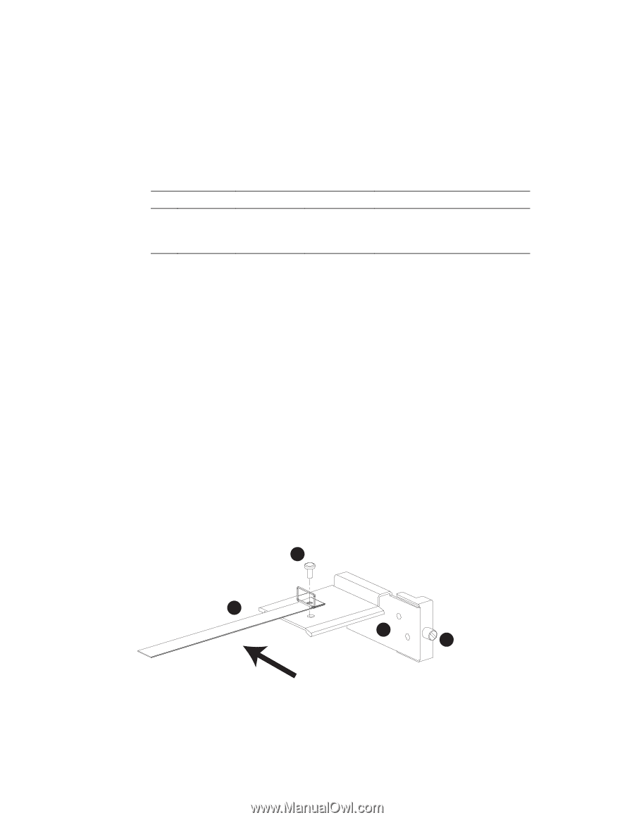
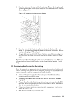
- One 13-inch strap that mounts to the lower side of the tray, designed to secure several interconnect cables in a large bundle. (Use as needed, in place of the second 8-inch strap.) The cable bundle will grow in diameter as you route cables from each successive server and there are differences in diameter between different types of interconnect cable. To bundle the cables, use a strap of the appropriate diameter. • The fasteners specified in Table 1-1. Table 1-1: HP Integrity rx2600 Cable Management Tray - Fasteners Qty. Size Type Torque Description 3 M5 x 10 mm Phillips 30 in-lb (Posidrive) Machine screw, pan-head 1 M6 Slotted 30 in-lb Screw, captive • A power supply cable. This cable is provided for use with the HP Integrity rx2600 server only in HP Cluster Platforms that use the Quadrics QsNetII® or an Infiniband® interconnect. Use this power cord in place of the power cord that is shipped with the server. • Packaging and documentation. To prevent screws from becoming loose due to vibration, HP recommends that you use an adjustable torque driver set to the torque specifications given in Table 1-1. Contact your HP sales representative if any parts are missing. 1.5 Orienting the Components A cable management tray is required for every server that has a PCI interconnect card, providing a connection port for the interconnect cable. The copper cable is heavy and has a limited bend radius. The cable management tray supports the cable, providing strain relief for the PCI port and ensuring a good connection. It also ensures the correct bend radius for the cable. Figure 1-1 shows the orientation of the cable management tray toward the rack. This figure shows only the 5-inch strap that attaches to the surface of the tray. Figure 1-1: Orientation of the Tray 2 1 3 4 To Rear of the Rack xc-cmt-01 The following parts are referenced in the installation procedure. The list numbers correspond to the callouts in Figure 1-1: 1. A 5-inch fabric strap. 2. A M5 x 10 mm screw. 1-2 Preparing to Install the Kit
-
 1
1 -
 2
2 -
 3
3 -
 4
4 -
 5
5 -
 6
6 -
 7
7 -
 8
8 -
 9
9
 |
 |