HP Cluster Platform Hardware Kits v2010 Integrity rx2600 Cable Management Tray - Page 8
Cabling and Power
 |
View all HP Cluster Platform Hardware Kits v2010 manuals
Add to My Manuals
Save this manual to your list of manuals |
Page 8 highlights
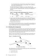
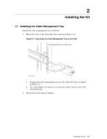
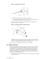
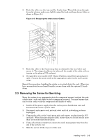
Figure 2-2: Attaching the 5-Inch Strap XC-CMT-003 a. Position the strap on the tray as shown in Figure 2-2. b. Use a #2 (medium) Phillips screwdriver to secure the strap to the tray's threaded hole, using an M5 x 10 mm machine screw. 3. Attach an 8-inch strap to the upper mounting hole in the side of the tray, as shown by callout 1 in Figure 2-3. Figure 2-3: Attaching Straps to the Side of the Tray 1 2 Depending on the tray's location in the rack, you might also need to attach an optional 13-inch strap as shown by callout 2 in Figure 2-3. You use this strap to secure several smaller cable bundles into one large bundle. Repeat this procedure until all the necessary trays are installed. 2.2 Cabling and Power Follow the cabling sequence instructions for the interconnect cables, as specified in the installation guide for your model of HP Cluster Platform (See Section 1.2 for the location of the documentation.) The cabling instructions are designed to ensure that the correct number of cables are grouped and bound together. The weight of each cable bundle must be supported by the various cable management straps located throughout the rack. When connecting the cable to the server's PCI card, use the following procedure: 1. Working from the top of the rack downward, connect each cable to the specified port on the PCI card. 2-2 Installing the Kit
-
 1
1 -
2
-
 3
3 -
 4
4 -
 5
5 -
 6
6 -
 7
7 -
 8
8 -
 9
9
 |
 |
