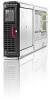
HP D2200sb HP BladeSystem c-Class architecture - Page 11
High bandwidth and performance, NonStop signal midplane scalability, Best practices - pcie storage blade
 |
View all HP D2200sb manuals
Add to My Manuals
Save this manual to your list of manuals |
Page 11 highlights
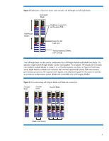
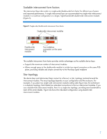
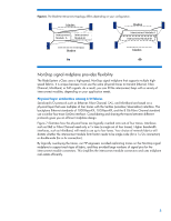
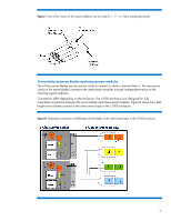
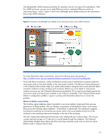
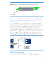
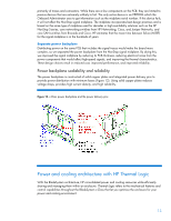
Some examples of storage and I/O device options using the dedicated links to a server blade include: StorageWorks SB40c Storage Blade consisting of a RAID controller and additional drives StorageWorks Ultrium Tape Blades that hold LTO-2, LTO-3, or LTO-4 Ultrium tape cartridges BladeSystem PCI Expansion Blade that can hold two off-the-shelf PCI-X or PCIe cards High bandwidth and performance HP engineers architected the BladeSystem c-Class enclosures to support future technologies and the anticipated demand for bandwidth and power. Three design elements make that possible: Blade form factors that enable server-class components (discussed in the "General-purpose flexible design" section) High-bandwidth NonStop signal midplane Separate power backplane NonStop signal midplane scalability The NonStop signal midplane supports signal rates of up to 10 Gb/s per lane (each lane consists of four SerDes transmit/receive traces). Therefore, each half-height server blade has the cross-sectional bandwidth to conduct up to 160 Gb/s per direction. In a c7000 enclosure fully configured with 16 half-height server blades, the aggregate bandwidth between device bays and interconnect bays is up to 5 Terabits/s across the NonStop signal midplane. The aggregate backplane bandwidth is calculated as follows: 160 Gb/s x 16 blades x 2 directions = 5.12 Terabits/s. This is bandwidth between the device bays and interconnect bays only. It does not include additional traffic capacity between interconnect modules or blade-to-blade connections. One of the areas our engineering teams focused on was high speed signal integrity. Getting this level of bandwidth between bays required special attention to high-speed signal integrity: Using general best practices for signal integrity to minimize end-to-end signal losses across the signal midplane Moving the power into an entirely separate backplane to independently optimize the NonStop signal midplane Providing a method to set optimal signal waveform shapes in the transmitters, depending on the topology of the end-to-end signal channel Best practices To ensure high-speed connectivity among all blades and interconnect modules, we leveraged our many years of experience in designing HP Superdome computers. Specifically, our engineers paid special attention to Controlling the differential signal impedance along each end-to-end signal trace across the PCBs and through the connector stages Using a ground plane to isolate receive and transmit signal pins (see Figure 10). Keeping signal traces short to minimize losses Routing signals in groups to minimize signal skew 11
-
 1
1 -
2
-
3
-
4
-
5
-
 6
6 -
 7
7 -
 8
8 -
 9
9 -
 10
10 -
 11
11 -
 12
12 -
 13
13 -
 14
14 -
 15
15 -
 16
16 -
17
-
18
-
19
-
20
-
21
-
22
-
23
 |
 |