HP DL785 Read Before Install - HP ProLiant DL-Series Carrier-Grade Servers - Page 3
Installation Guidelines - chassis
 |
UPC - 883585262809
View all HP DL785 manuals
Add to My Manuals
Save this manual to your list of manuals |
Page 3 highlights
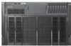
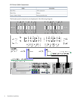
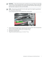
1 Installation Guidelines This document provides general guidelines and tips for installing HP ProLiant DL-Series Carrier-Grade Servers. This document addresses the following topics: • Cabling • Connecting to the HP breaker panel • Installing the cable management retainer clip Cabling This section provides cabling information for installing HP ProLiant DL-Series Carrier-Grade Servers. NEBS Chassis Ground This carrier-grade product is intended for use in both Common Bonding Networks and Isolated Bonding Networks. It is equipped with a NEBS-compliant chassis ground lug located on the rear of the product. Attach the NEBS ground cable from the chassis to the rack ground bus bar using either the ground cable provided, or a customer-provided cable. The ground lug included accepts wire gauges between 10 and 12 AWG. Gigabit Ethernet Port Cabling Gigabit Ethernet Ports (intra-building ports) of the HP ProLiant DL-Series Carrier-Grade Servers require the use of shielded Cat5e cables grounded at both ends. Furthermore, please note the following: CAUTION: The intra-building ports of the equipment are suitable for connection to intra-building or unexposed wiring or cabling only. The intra-building ports of the equipment MUST NOT be metallically connected to interfaces that connect to the Outside Plant (OSP) or its wiring. These interfaces are designed for use as intra-building interfaces only (Type 2 or Type 4 ports as described in GR-1089-CORE, Issue 4) and require isolation from the exposed OSP cabling. The addition of Primary Protectors is not sufficient protection in order to connect these interfaces metallically to OSP wiring. Connecting to the HP Breaker Panel This section provides information for the following: • Connecting the power supply and cables to the breaker panel • Installing the breaker in the breaker panel WARNING! Ensure the breaker is not installed or open when connecting DC cables to the breaker panel. Connecting the Power Supply and Cables to the Breaker Panel DL-Series carrier-grade servers are provided with two power supplies and DC cables. While each installation has some variability, the suggested topology is to utilize the lower current-rated breaker panel positions as follows: 30A DC maximum: breaker / terminal positions 4-7 (side A and B) The following table lists the DC power cable connections. Cabling 3
-
 1
1 -
 2
2 -
 3
3 -
 4
4 -
 5
5 -
 6
6 -
 7
7 -
 8
8
 |
 |