HP Designjet 700 Service Manual - Page 95
WĂAĂRĂNĂIĂNĂG, Calibration, Reassembling
 |
View all HP Designjet 700 manuals
Add to My Manuals
Save this manual to your list of manuals |
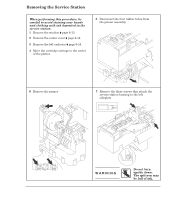
Page 95 highlights
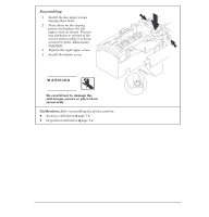
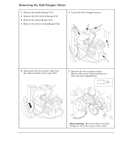
Reassembling: 1 Install the two upper screws leaving them loose. 2 Press down on the sloping plastic and tighten the left upper screw as shown. Prevent any slackness or motion of the service station while it is being screwed in place. This is very important. 3 Tighten the right upper screw. 4 Install the bottom screw. WĂAĂRĂNĂIĂNĂG Be careful not to damage the selfĆtorque screws or place them incorrectly Calibration: After reassembling the plotter, perform: D Accuracy calibration ' page 7Ć6. D DropĆdetect calibration ' page 7Ć4. C4705-90000 Removal and Replacement 6-43
-
 1
1 -
2
-
3
-
4
-
5
-
6
-
7
-
8
-
9
-
10
-
11
-
12
-
13
-
14
-
15
-
16
-
17
-
18
-
19
-
20
-
21
-
22
-
23
-
24
-
25
-
26
-
27
-
28
-
29
-
30
-
31
-
32
-
33
-
34
-
35
-
36
-
37
-
38
-
39
-
40
-
41
-
42
-
43
-
44
-
45
-
46
-
47
-
48
-
49
-
50
-
51
-
52
-
53
-
54
-
55
-
56
-
57
-
58
-
59
-
60
-
61
-
62
-
63
-
64
-
65
-
66
-
67
-
68
-
69
-
70
-
71
-
72
-
73
-
74
-
75
-
76
-
77
-
78
-
79
-
80
-
81
-
82
-
83
-
84
-
85
-
86
-
87
-
88
-
89
-
 90
90 -
 91
91 -
 92
92 -
 93
93 -
 94
94 -
 95
95 -
 96
96 -
 97
97 -
 98
98 -
 99
99 -
 100
100 -
101
-
102
-
103
-
104
-
105
-
106
-
107
-
108
-
109
-
110
-
111
-
112
-
113
-
114
-
115
-
116
-
117
-
118
-
119
-
120
-
121
-
122
-
123
-
124
-
125
-
126
-
127
-
128
-
129
-
130
-
131
-
132
-
133
-
134
-
135
-
136
-
137
-
138
-
139
-
140
-
141
-
142
-
143
-
144
-
145
-
146
-
147
-
148
-
149
-
150
-
151
-
152
-
153
-
154
-
155
-
156
-
157
-
158
-
159
-
160
-
161
-
162
-
163
-
164
-
165
-
166
-
167
-
168
-
169
-
170
-
171
-
172
-
173
-
174
-
175
-
176
-
177
-
178
-
179
-
180
-
181
-
182
-
183
-
184
-
185
-
186
-
187
-
188
-
189
-
190
-
191
-
192
-
193
-
194
-
195
-
196
-
197
-
198
-
199
-
200
-
201
-
202
-
203
-
204
-
205
-
206
-
207
-
208
-
209
-
210
-
211
-
212
-
213
-
214
-
215
-
216
-
217
-
218
-
219
-
220
-
221
-
222
-
223
-
224
-
225
-
226
-
227
-
228
-
229
-
230
-
231
-
232
-
233
-
234
-
235
-
236
-
237
-
238
-
239
-
240
-
241
-
242
-
243
-
244
-
245
-
246
-
247
-
248
-
249
-
250
-
251
-
252
-
253
-
254
-
255
-
256
-
257
-
258
-
259
-
260
-
261
-
262
-
263
-
264
-
265
-
266
-
267
-
268
-
269
-
270
-
271
-
272
-
273
-
274
-
275
-
276
-
277
-
278
-
279
-
280
-
281
-
282
-
283
-
284
-
285
-
286
-
287
-
288
 |
 |

Calibration:
After reassembling the plotter, perform:
D
Accuracy calibration
'
page 7Ć6.
D
DropĆdetect calibration
'
page 7Ć4.
Reassembling:
1
Install the two upper screws
leaving them loose.
2
Press down on the sloping
plastic and tighten the left
upper screw as shown. Prevent
any slackness or motion of the
service station while it is being
screwed in place. This is very
important.
3
Tighten the right upper screw.
4
Install the bottom screw.
Be careful not to damage the
selfĆtorque screws or place them
incorrectly
WĂAĂRĂNĂIĂNĂG
6-43
Removal and Replacement
C4705-90000