HP Designjet 815mfp HP Designjet 815mfp - Assembly and Maintenance Poster - Page 2
of the stand, using the same parts, just 'mirror
 |
View all HP Designjet 815mfp manuals
Add to My Manuals
Save this manual to your list of manuals |
Page 2 highlights
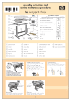
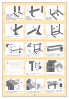
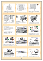
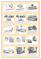
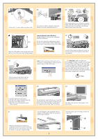
1 2 3 Attach the two feet to the left and right legs using four M6×30 screws (two for each foot). Tighten the screws with the Allen key found in the assembly kit. Secure the two legs by fastening the cross bar with four M6×10 screws (two each side). Lay the two legs down into the position shown. 4 5 6 Attach the bottom bar to the leg using two M6×10 screws. 7 M6×30 Attach the bottom bar to the other leg using two M6×10 screws. Raise the legs carefully into the upright position. 8 9 M6×10 Fasten the top bar and wire guide to the two legs using four M6×30 and two M6×10 screws. Remove the plastic safety tie and tighten up all screws firmly. Connect the rear table. This is fitted by locating the four guide pins on the rear of the table into the rubber-framed holes on the top bar. At this point you must decide on which side you are going to fit the touch screen assembly. This can be fitted on the left or right side of the stand. The next steps, 10 to 17, explain how to fit the touch screen assembly to the right side of the stand. To fit the touch screen assembly to the left side of the stand, using the same parts, just 'mirror' the assembly procedure described here. 10 Attach the touch screen arm to the stand legs using two M6×12 screws. 11 Attach the brace using two M4×6 screws. 12 13 14 hp designjet copier cc800ps Slide the keyboard assembly down as far as it will go on the touch screen arm. Lock the keyboard assembly to the touch screen arm using one M4×8 (headless) screw. 2 Lift the scanner into place, locating the rubber feet in the holes indicated, and fixing with the four special screws.
-
 1
1 -
 2
2 -
 3
3 -
 4
4 -
 5
5 -
 6
6
 |
 |
