HP Designjet 815mfp HP Designjet 815mfp - Assembly and Maintenance Poster - Page 3
caution - 42
 |
View all HP Designjet 815mfp manuals
Add to My Manuals
Save this manual to your list of manuals |
Page 3 highlights
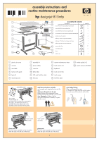
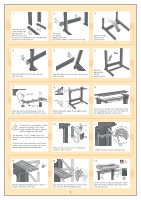
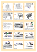
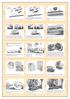
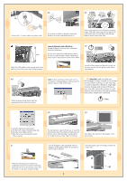
15 16 17 Rest the touch screen face down on a table. Attach the touch screen bracket to the rear of the touch screen using two M4×8 screws as shown. Attach with three more M4×8 screws as shown. Slide the hub of the touch screen assembly into the touch screen arm. 18 19 20 Secure the hub of the touch screen bracket using an M3×8 screw. Slide the assembled printer under the scanner. The printer's feet will be positioned outside the scanner's feet. Your HP Designjet 815mfp is now assembled and should appear as in the above illustration. cleaning the scan area... You are now required to clean the scan area. To do so, you will need the cleaning tools provided in the maintenance kit and a cleaning fluid (not included in the maintenance kit). caution: do not use abrasives, acetone, benzene, or fluids that contain these chemicals. Do not spray liquids directly onto the scanner's glass plate or anywhere else in the scanner. 8 10D12TEI14X1D6EN E T X E 6 Inches0D.080.E160.D24T0. I3N10.X3E90E.47T0.550X.63E 4 N 2 O MmmR A L L AMRON 21 Open the scanner cover to expose the scan area. NORMA L mm D 2 E 64 INTD E X T E N0E.6DX03.I5E05.T407.D309.301.204.N106.0O8 IRncMheAs L 16E14 1X2 1TE0X8E 23 24 22 E X 16 T 14 E E D N E T I X 4D L A M R O mm N 6 8 10 12 2 L A M R N mm O 6D TE ID N E X 16 E T X E 2 4 14 12 10 8 0.55 0.63 0.39 0.47 E X EE T T I X E 0.31 0.16 D 0.24 0.08 Inches D N O N R M A L N Inches O R M A L 0.08 0.24 D 0.16 0.39 0.31 0.63 0.55 0.47 I T E X D E T E N X E 16E14 1X2 1TE0X8E I 6NT 4D2E mm D NORMA L E X T E N0E.6DX03.I5E05.T407.D309.301.204.N106.0O8 IRncMheAs L L A MmmR 2 O 4 N 6 8 10D12TEI14X1D6EN E T X E L AMRON Inches0D.080.E160.D24T0. I3N10.X3E90E.47T0.550X.63E Position your fingers in the four lock slots (two at each end of the platen indicated by the green arrows above), and press down (blue arrows). 2 caution: see note after step 20 E 16E14 1X2 1TE0X8E 64 INTD 2 E mm D NORMA L E X T E N0E.6DX03.I5E05.T407.D309.301.204.N106.0O8 IRncMheAs L L A MmmR 2 O 4 N 6 8 10D12TEI14X1D6EN E T X E L A M R O N Inches0D.080.E160.D24T0. I3N10.X3E90E.47T0.550X.63E 16E14 1X2 1TE0X8E I 6NT 4D2E mm D NORMA L E X T E N0E.6DX03.I5E05.T407.D309.301.204.N106.0O8 IRncMheAs L L A MmmR 2 O 4 N 6 8 10D12TEI14X1D6EN E T X E L AMRON Inches0D.080.E160.D24T0. I3N10.X3E90E.47T0.550X.63E With the platen pushed down, slide the two locks inwards until the pins at either end pop up, locking the platen open and ready to be removed. Raise the two handles, and remove the pressure platen. Clean the glass with a lint-free cloth and a mild, streak-free, glass cleaner. 26 27 16E14 1X2 1TE0X8E 64 INTD 2 E mm D NORMA L E X T E N0E.6DX03.I5E05.T407.D309.301.204.N106.0O8 IRncMheAs L L A MmmR 2 O 4 N 6 8 10D12TEI14X1D6EN E T X E L AMRON Inches0D.080.E160.D24T0. I3N10.X3E90E.47T0.550X.63E Dry the glass fully using a separate clean, dry lint-free cloth like the one provided with the maintenance kit. Turn the pressure platen over to expose the white background plate. 3 Clean the white background plate with a lint-free cloth and a mild, streak-free, glass cleaner.
-
 1
1 -
 2
2 -
 3
3 -
 4
4 -
 5
5 -
 6
6
 |
 |
