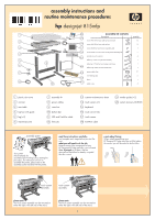
HP Designjet 815mfp HP Designjet 815mfp - Assembly and Maintenance Poster - Page 4
keep out dust and reduce maintenance, Caution - rollers
 |
View all HP Designjet 815mfp manuals
Add to My Manuals
Save this manual to your list of manuals |
Page 4 highlights
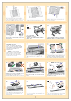
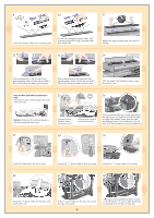
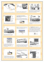
30 31 a 16E14 1X2 1TE0X8E 642 INTD E mm D NORMA L E X T E N0E.6DX03.I5E05.T407.D309.301.204.N106.0O8 IRncMheAs L L A MmmR 2 O 4 N 6 8 10D12TEI14X1D6EN E T X E L A M R O N Inches0D.080.E160.D24T0. I3N10.X3E90E.47T0.550X.63E Clean the transport rollers and surrounding area. Dry the white background plate, rollers, and surrounding area fully using a separate clean, dry lint-free cloth. Replace the pressure platen and lower the two handles. 32 a b TXE 8 10D12TEI14X1D6EN E T X E 6 4 N 2 O MmmR A L L AMRON 33 a TXE b L AMRON L A MR mm O 2 N 4 6 IncheDs0.0E80.16D0.2T40N.3I10XE.39E0.4T70.5X50.6E3 8 1D0 1T2E1I4DX16EN E T X E 34 E X TEEXN0TE.6DX03.EI5E05.TN4007E..D63DX0309..I53E0501..T420704.D.N310906..30O018.2IR04.nN1c06. Mh0Oe8AsIRnLcMheAs L 16E14 1X211T6E0E1X84EI1X62NT1T4E0DX82EIE6NTD4D m2mE DNmmORNMOARLMA L Inches0D.080.E160.D24T0. I3N10.X3E90E.47T0.550X.63E L A LMARMORN IOnchNesI0D.n0c80h.Ee16s00.LD.D204T800..EAI3N1106.0.LX3D2ME904TE0.m.4AI3Nm7RT100..5X35M2E90OX0.E.m6434m7RT0NE.56520OX.6834NE106D128TE1I140DX1D162TEE1IN4X1DE6ENT EX TE X E 8 10D12TE1I4X1D6EN E T X E Pushing downwards on the left side of the pressure platen, push in the pin (a) and slide in the lock (b) locking the platen end into place. 6 Inches0D.080.E160.D24T0. I3N10.X3E90E.47T0.550X.63E 4 N 2 O MmmR A L L AMRON Pushing downwards on the right side of the pressure platen, push in the pin (a) and slide in the lock (b) locking the platen end into place. NORMA L mm D 2 E 64 INTD E X T E N0E.6DX03.I5E05.T407.D309.301.204.N106.0O8 IRncMheAs L 16E14 1X2 1TE0X8E hphpdedseisgingjnejtect ocpoipeirercc8c8000psps With the platen firmly locked into place, close the scanner cover. keep out dust and reduce maintenance 35 36 time... Cover your scanner with the plastic dust cover when not in use. Caution: make sure the scanner power is off when using the dust cover. Connect the touch screen to the scanner using the FireWire cable, fastening with the clips on the touch screen arm. If you have placed the touch screen assembly on the right leg you will find that the FireWire cable is longer than needed. Please keep the cable bundled and place it in the cable duct. You will have to lift the rear table to access the cable duct. 37 38 39 Connect the keyboard to the touch screen. 40 Connect the "Y" power cable to the touch screen. Connect the "Y" power cable to the scanner. 41 42 Attach the "Y" power cable into the clips on the touch screen arm. Fit the 'Y' power cable into the clips. Then attach the clips to the stand. 4 on the left leg, the "Y" power cable should only be attached to the left leg and cross bar.
-
 1
1 -
 2
2 -
 3
3 -
 4
4 -
 5
5 -
 6
6
 |
 |
