HP ENVY 15-as000 Maintenance and Service Guide
HP ENVY 15-as000 Manual
 |
View all HP ENVY 15-as000 manuals
Add to My Manuals
Save this manual to your list of manuals |
HP ENVY 15-as000 manual content summary:
- HP ENVY 15-as000 | Maintenance and Service Guide - Page 1
HP ENVY Notebook PC (model numbers 15as000 through 15-as099) Maintenance and Service Guide IMPORTANT! This document is intended for HP authorized service providers only. - HP ENVY 15-as000 | Maintenance and Service Guide - Page 2
SD Logo is a trademark of its proprietor. This guide describes features that are common to most models. Some HP products and services are set forth in the express warranty statements accompanying such products and services. Nothing herein should be construed as constituting an additional warranty. HP - HP ENVY 15-as000 | Maintenance and Service Guide - Page 3
Safety warning notice WARNING! To reduce the possibility of heat-related injuries or of overheating the device, do not place the device directly on your lap or obstruct the device air vents. Use the device only on a hard, flat surface. Do not allow another hard surface, such as an adjoining optional - HP ENVY 15-as000 | Maintenance and Service Guide - Page 4
iv Safety warning notice - HP ENVY 15-as000 | Maintenance and Service Guide - Page 5
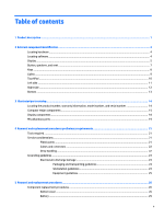
information, model number, and serial number 14 Computer major components ...15 Display components ...18 Miscellaneous parts ...19 4 Removal and replacement procedures preliminary requirements 21 Tools required ...21 Service considerations ...21 Plastic parts ...21 Cables and connectors ...22 - HP ENVY 15-as000 | Maintenance and Service Guide - Page 6
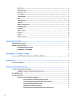
...61 Updating Setup Utility (BIOS) ...61 Determining the BIOS version ...61 Downloading a BIOS update ...62 7 Using HP PC Hardware Diagnostics (UEFI) ...63 Downloading HP PC Hardware Diagnostics (UEFI) to a USB device 63 8 Specifications ...65 Computer specifications ...65 9 Backing up, restoring - HP ENVY 15-as000 | Maintenance and Service Guide - Page 7
10 Power cord set requirements ...73 Requirements for all countries ...73 Requirements for specific countries and regions 73 11 Recycling ...75 Index ...76 vii - HP ENVY 15-as000 | Maintenance and Service Guide - Page 8
viii - HP ENVY 15-as000 | Maintenance and Service Guide - Page 9
Name Processor Chipset Graphics Panel Memory Hard drive Description HP ENVY Notebook PC (Model numbers used 15-as000 through 15-as099) ● Intel® Core™ i7-6500U 2.50-GHz (SC turbo up to 3.10-GHz) processor (1600-MHz FSB, 4.0MB L3 cache, dual core, 15-W) ● Intel Core i5-6260U 1.80-GHz (SC turbo up - HP ENVY 15-as000 | Maintenance and Service Guide - Page 10
PCIe, NVMe solid-state drive supporting TLC ● 256-MB, M.2, SATA solid-state drive supporting TLC ● 128-MB, M.2, solid-state drive HP TrueVision HD webcam with indicator light, ● HDMI v1.4 supporting up to 1920×1080 @ 60 Hz ● USB 3.0 ports (3) ● USB 3.0 port Type-C Full-sized, backlit, island-style - HP ENVY 15-as000 | Maintenance and Service Guide - Page 11
Keyboard/pointing devices (continued) Power requirements Security Operating system Serviceability Description ● ClickPad with image sensor ● Multitouch gestures enabled ● Support for Windows modern trackpad gestures ● Taps enabled as default Support for a 3-cell, 52-WHr, 4.56-AHr, Li-ion battery - HP ENVY 15-as000 | Maintenance and Service Guide - Page 12
2 External component identification Locating hardware To find out what hardware is installed on the computer: ▲ Type device manager in the taskbar search box, and then select the Device Manager app. A list displays all the devices installed on the computer. For information about system hardware - HP ENVY 15-as000 | Maintenance and Service Guide - Page 13
obstructions. For wireless regulatory notices, see the section of the Regulatory, Safety, and Environmental Notices that applies to your country or region. To access this guide: ▲ Select the Start button, select All apps, select HP Help and Support, and then select HP Documentation. Display 5 - HP ENVY 15-as000 | Maintenance and Service Guide - Page 14
notices, see the section of the Regulatory, Safety, and Environmental Notices that applies to your country or region. To access this guide: ▲ Select the Start button, select All apps, select HP Help and Support, and then select HP Documentation. 6 Chapter 2 External component identification - HP ENVY 15-as000 | Maintenance and Service Guide - Page 15
Button, speakers, and vent Item (1) Component Power button (2) Speakers (3) Vent Description ● When the computer is off, press the button to turn on the computer. ● When the computer is on, press the button briefly to initiate Sleep. ● When the computer is in the Sleep state, press the button - HP ENVY 15-as000 | Maintenance and Service Guide - Page 16
Item Component Keys Description NOTE: The computer fan starts up automatically to cool internal components and prevent overheating. It is normal for the internal fan to cycle on and off during routine operation. Item (1) Component esc key (2) fn key (3) Windows key (4) Action keys (5) num - HP ENVY 15-as000 | Maintenance and Service Guide - Page 17
Lights Item (1) Component Power light (2) Mute light (3) Caps lock light Description ● On: The computer is on. ● Blinking: The computer is in the Sleep state, a powersaving state. The computer shuts off power to the display and other unneeded components. ● Off: The computer is off or in - HP ENVY 15-as000 | Maintenance and Service Guide - Page 18
TouchPad Item (1) Component TouchPad zone (2) Left TouchPad button (3) Right TouchPad button Description Reads your finger gestures to move the pointer or activate items on the screen. Functions like the left button on an external mouse. Functions like the right button on an external mouse. - HP ENVY 15-as000 | Maintenance and Service Guide - Page 19
stolen. Connects optional USB devices, such as a keyboard, mouse, external drive, printer, scanner, or USB hub. ● Blinking white: The hard drive is being accessed. ● Amber: HP 3D DriveGuard has temporarily parked the hard drive. Left side 11 - HP ENVY 15-as000 | Maintenance and Service Guide - Page 20
additional safety information, refer to the Regulatory, Safety, and Environmental Notices. To access this guide: ▲ Select the Start button, select All apps, select HP Help and Support, and then select HP Documentation. NOTE: When a device is connected to the jack, the computer speakers are disabled - HP ENVY 15-as000 | Maintenance and Service Guide - Page 21
Item (6) Component AC adapter and battery light (continued) (7) Power connector Bottom Description ● Blinking white: The AC adapter is disconnected and the battery has reached a low battery level. ● Amber: The AC adapter is connected and the battery is charging. ● Off: The battery is not - HP ENVY 15-as000 | Maintenance and Service Guide - Page 22
improves and changes product parts. For complete and current information on supported parts for your computer, go to http://partsurfer.hp.com, select your country or region, and then follow the on-screen instructions. Locating the product number, warranty information, model number, and serial number - HP ENVY 15-as000 | Maintenance and Service Guide - Page 23
display assembly spare part information, see Display components on page 18. 15.6-in, RGBW, UHD, WLED, AntiGlare (3840×2160), uslim-flat UWVA, eDP+PSR 858712-001 TouchScreen display assembly equipped with HDC and infrared webcam 15.6-in, RGBW, UHD, WLED, AntiGlare (3840×2160), uslim-flat (2.68-mm - HP ENVY 15-as000 | Maintenance and Service Guide - Page 24
.6-in, FHD, WLED, BrightView (1920×1080), slim-flat (3.0-mm), UWVA, eDP TouchScreen 858711-001 display assembly equipped with HDC and infrared webcam 15.6-in, FHD, WLED, BrightView (1920×1080), slim-flat (3.0-mm), UWVA, eDP TouchScreen 857439-001 display assembly equipped with HDC and non-infrared - HP ENVY 15-as000 | Maintenance and Service Guide - Page 25
includes: 857795-001 (10) System board short support bridge (11) System board long support bridge (12) Power connector cable bracket (13) GHz) processor (1600- 857242-001 MHz FSB, 4.0-MB L3 cache, dual core, 15-W) and a non-Windows operating system Equipped with an Intel Core i5-6260U 1.80- - HP ENVY 15-as000 | Maintenance and Service Guide - Page 26
Item (20) (21) (22) (23) (24) (25) (26) (27) Component 2-GB (2133, 1.2-V, DDR4) Intel Dual Band Wireless-AC 7265 802.11 ac 2×2 WiFi + Bluetooth 4.2 Combo Adapter Heat sink (includes replacement thermal material) Fan (includes cable) Battery (3-cell, 52-WHr, 4.56-AHr, Li-ion; includes cable) Hard - HP ENVY 15-as000 | Maintenance and Service Guide - Page 27
), UWVA, eDP+PSR 857483-001 display panel 15.6-in, FHD, WLED, BrightView (1920×1080), HP duck head adapter for use in South Korea HP duck head adapter for use in the United States HP HDMI-to-VGA adapter HP RJ45-to-USB adapter dongle HP USB-Type C-to-USB 3.0 adapter HP USB-to-Gigabit RJ45 adapter HP - HP ENVY 15-as000 | Maintenance and Service Guide - Page 28
Component For use in Europe For use in India For use in Israel For use in Italy For use in Japan For use in North America For use in the People's Republic of China For use in South Africa For use in Switzerland For use in Taiwan For use in Thailand For use in the United Kingdom and Singapore Screw - HP ENVY 15-as000 | Maintenance and Service Guide - Page 29
● Magnetic screwdriver ● Phillips P00, P0, and P1 screwdrivers ● Torx T4 screwdriver Service considerations The following sections include some of the considerations that you must keep in mind parts. Apply pressure only at the points designated in the maintenance instructions. Tools required 21 - HP ENVY 15-as000 | Maintenance and Service Guide - Page 30
Cables and connectors CAUTION: When servicing the computer, be sure that cables are placed in their proper locations during the reassembly process. Improper cable placement can damage the computer. Cables must - HP ENVY 15-as000 | Maintenance and Service Guide - Page 31
-lined box Typical electrostatic voltage levels 10% 35,000 V 12,000 V 6,000 V 2,000 V 11,500 V 14,500 V 26,500 V 21,000 V Relative humidity 40% 15,000 V 5,000 V 800 V 700 V 4,000 V 5,000 V 20,000 V 11,000 V 55% 7,500 V 3,000 V 400 V 400 V 2,000 V 3,500 V 7,000 V 5,000 V Grounding guidelines 23 - HP ENVY 15-as000 | Maintenance and Service Guide - Page 32
material. ● Use a wrist strap connected to a properly grounded work surface and use properly grounded tools and equipment. ● Use conductive field service tools, such as cutters, screwdrivers, and vacuums. ● When fixtures must directly contact dissipative surfaces, use fixtures made only of static - HP ENVY 15-as000 | Maintenance and Service Guide - Page 33
with ground cords of one megohm resistance ● Static-dissipative tables or floor mats with hard ties to the ground ● Field service kits ● Static awareness labels ● Material-handling packages ● Nonconductive plastic bags, tubes, or boxes ● Metal tote boxes ● Electrostatic voltage levels and - HP ENVY 15-as000 | Maintenance and Service Guide - Page 34
replacement procedures. There are as many as 69 screws that must be removed, replaced, and/or loosened when servicing the computer. Make special note of each screw size and location during removal and replacement. Bottom cover Description Bottom cover (includes front rubber foot strip, shielding - HP ENVY 15-as000 | Maintenance and Service Guide - Page 35
4. Remove the following screws that secure the bottom cover to the computer: (2) Two Torx5 M2.0×7.3 screws in the rear corners of the bottom cover (3) Four Phillips M2.5×7.8 screws under the rubber foot strip (4) Four Torx5 M2.0×5.4 screws on the front edge of the bottom cover 5. Insert a case - HP ENVY 15-as000 | Maintenance and Service Guide - Page 36
7. Remove the bottom cover (3). Reverse this procedure to install the bottom cover. 28 Chapter 5 Removal and replacement procedures - HP ENVY 15-as000 | Maintenance and Service Guide - Page 37
Battery Description Battery (3-cell, 52-WHr, 4.56-AHr, Li-ion; includes cable) Spare part number 849313-856 Before removing the battery, follow these steps: 1. Turn off the computer. If you are unsure whether the computer is off or in Hibernation, turn the computer on, and then shut it down - HP ENVY 15-as000 | Maintenance and Service Guide - Page 38
Hard drive NOTE: The hard drive spare part kit does not include the hard drive rubber bracket or hard drive cable. The hard drive rubber bracket is available using spare part number 857797-001. The hard drive cable is available using spare part number 857806-001. Description 1-TB, 5400-rpm, SATA, - HP ENVY 15-as000 | Maintenance and Service Guide - Page 39
4. If it is necessary to replace the hard drive rubber bracket, release the left and right sides (2) of the rubber bracket from the hard drive, and then remove the rubber bracket (3). Reverse this procedure to reassemble and install the hard drive. Memory module Description 8-GB (2133, 1.2-V, DDR4) - HP ENVY 15-as000 | Maintenance and Service Guide - Page 40
2. Remove the memory module (2) by pulling it away from the slot at an angle. Reverse this procedure to install a memory module. 32 Chapter 5 Removal and replacement procedures - HP ENVY 15-as000 | Maintenance and Service Guide - Page 41
Solid-state drive Description 512-GB, M2, PCIe, NVMe solid-state drive supporting TLC 256-GB, M2, SATA-3 solid-state drive supporting TLC 256-GB, M2, PCIe, NVMe solid-state drive supporting TLC 128-GB, M2, SATA-3 solid-state drive Spare part number 857487-001 857485-001 857486-001 857484-001 - HP ENVY 15-as000 | Maintenance and Service Guide - Page 42
RTC battery Description RTC battery (includes cable and double-sided adhesive) Spare part number 857798-001 Before removing the USB board, follow these steps: 1. Turn off the computer. If you are unsure whether the computer is off or in Hibernation, turn the computer on, and then shut it down - HP ENVY 15-as000 | Maintenance and Service Guide - Page 43
country or region. If you replace the module and then receive a warning message, remove the module to restore device functionality, and then contact technical support. Before removing the WLAN module, follow these steps: 1. Turn off the computer. If you are unsure whether the computer is off or in - HP ENVY 15-as000 | Maintenance and Service Guide - Page 44
3. Remove the WLAN module (3) by pulling the module away from the slot at an angle. NOTE: If the WLAN antenna cables are not connected to the WLAN module terminal, the protective sleeves should be installed on the antenna connectors, as shown in the following illustration. Reverse this procedure to - HP ENVY 15-as000 | Maintenance and Service Guide - Page 45
Fan Description Fan (includes cable) Spare part number 857805-001 Before removing the fan, follow these steps: 1. Turn off the computer. If you are unsure whether the computer is off or in Hibernation, turn the computer on, and then shut it down through the operating system. 2. Disconnect the - HP ENVY 15-as000 | Maintenance and Service Guide - Page 46
TouchPad cable Description TouchPad cable (includes double-sided adhesive) Spare part number 857807-001 Before removing the TouchPad cable, follow these steps: 1. Turn off the computer. If you are unsure whether the computer is off or in Hibernation, turn the computer on, and then shut it down - HP ENVY 15-as000 | Maintenance and Service Guide - Page 47
TouchPad NOTE: The TouchPad spare part kit does not include the TouchPad bracket or TouchPad cable. The TouchPad bracket is available using spare part number 857796-001. The TouchPad cable is available using spare part number 857807-001. Description TouchPad Spare part number 857801-001 Before - HP ENVY 15-as000 | Maintenance and Service Guide - Page 48
Reverse this procedure to install the TouchPad. Power connector cable Description Power connector cable Spare part number 857438-010 Before removing the power connector cable, follow these steps: 1. Turn off the computer. If you are unsure whether the computer is off or in Hibernation, turn the - HP ENVY 15-as000 | Maintenance and Service Guide - Page 49
6. Remove the power connector cable (4). Reverse this procedure to install the power connector cable. Component replacement procedures 41 - HP ENVY 15-as000 | Maintenance and Service Guide - Page 50
USB board cables Description USB board cable (190 mm, includes double-sided adhesive) USB board cable (173 mm, includes double-sided adhesive) Spare part number 858701-001 857802-001 Before removing the USB board cables, follow these steps: 1. Turn off the computer. If you are unsure whether the - HP ENVY 15-as000 | Maintenance and Service Guide - Page 51
USB board NOTE: The USB board spare part kit includes the USB board cables. The USB board cables are also available using spare part numbers 858701-001 and 857802-001. Description USB board (includes cables and 2 USB ports) Spare part number 857794-001 Before removing the USB board, follow these - HP ENVY 15-as000 | Maintenance and Service Guide - Page 52
6. Remove the USB board bracket (4). The USB board bracket is included in the I/O Bracket Kit, spare part number 857795-001. 7. Remove the USB board (5). Reverse this procedure to install the USB board. 44 Chapter 5 Removal and replacement procedures - HP ENVY 15-as000 | Maintenance and Service Guide - Page 53
to 3.10-GHz) processor (1600-MHz FSB, 4.0-MB L3 cache, dual core, 15-W) and the Windows 10 operating system Equipped with an Intel Core i7-6500U 2.50 2.80-GHz) processor (1600-MHz FSB, 3.0-MB L3 cache, dual core, 15-W) and a non-Windows operating system Spare part number 857242-601 857242-001 857241 - HP ENVY 15-as000 | Maintenance and Service Guide - Page 54
to the keyboard/top cover. 4. Remove the four Phillips M2.5×3.8 screws (3) that secure the system board to the keyboard/top cover. 5. Remove the large plastic support bridge (4). 46 Chapter 5 Removal and replacement procedures - HP ENVY 15-as000 | Maintenance and Service Guide - Page 55
6. Remove the small plastic support bridge (5). 7. Release the system board (1) by lifting the right side and swinging it up and to the left until it rests at an angle. 8. Remove - HP ENVY 15-as000 | Maintenance and Service Guide - Page 56
Heat sink Description Heat sink (includes replacement thermal material) Spare part number 857245-001 Before removing the heat sink, follow these steps: 1. Turn off the computer. If you are unsure whether the computer is off or in Hibernation, turn the computer on, and then shut it down through the - HP ENVY 15-as000 | Maintenance and Service Guide - Page 57
the system board each time the heat sink is removed. Thermal material is used on the processor (1) and the heat sink section (2) that services it. Reverse this procedure to install the heat sink. Speakers Description Speakers (includes left and right speakers and cables) Spare part number 857804 - HP ENVY 15-as000 | Maintenance and Service Guide - Page 58
.6-in, RGBW, UHD, WLED, AntiGlare (3840×2160), uslim-flat (2.68-mm), UWVA, eDP+PSR TouchScreen 858712-001 display assembly equipped with HDC and webcam 15.6-in, RGBW, UHD, WLED, AntiGlare (3840×2160), uslim-flat (2.68-mm), UWVA, eDP+PSR TouchScreen 857440-001 display assembly equipped with HDC and - HP ENVY 15-as000 | Maintenance and Service Guide - Page 59
3. Disconnect all external devices from the computer. 4. Remove the bottom cover (see Bottom cover on page 26). 5. Disconnect the battery cable from the system board (see Battery on page 29). Remove the display assembly: 1. Disconnect the WLAN antenna cables (1) from the terminals on the WLAN module - HP ENVY 15-as000 | Maintenance and Service Guide - Page 60
7. Release the display hinges (2) by swinging them up and back. 8. Swing the keyboard/top cover (1) up and away from the display assembly. 9. Slide the keyboard/top cover (2) forward and separate it from the display assembly. 10. If it is necessary to replace the display bezel: a. Flex the inside - HP ENVY 15-as000 | Maintenance and Service Guide - Page 61
c. Remove the display bezel (5). The display bezel is available using spare part number 857813-001. 11. If it is necessary to replace the display panel: a. Remove the display bezel. b. Remove the four Phillips M2.0×2.9 screws that secure the display panel to the display back cover. CAUTION: Before - HP ENVY 15-as000 | Maintenance and Service Guide - Page 62
in, RGBW, UHD, WLED, AntiGlare (3840×2160), uslim-flat (2.68-mm), UWVA, eDP+PSR display panel) and 857482-001 (15.6-in, FHD, WLED, BrightView (1920×1080), slim-flat (3.0-mm), UWVA, eDP display panel). 12. If it is necessary to replace the display panel cable: a. Remove - HP ENVY 15-as000 | Maintenance and Service Guide - Page 63
f. Remove the display panel cable (4). The display panel cable is available using spare part numbers 857809-001 (for use only on computer models equipped with a UHD display panel) and 857808-001 (for use only on computer models equipped with an FHD display panel). 13. If it is necessary to replace - HP ENVY 15-as000 | Maintenance and Service Guide - Page 64
e. Detach the webcam/microphone module (3) from the display back cover. The webcam/microphone module is secured to the display back cover with double-sided adhesive.) f. Remove the webcam/microphone module. The webcam/microphone module is available using spare part number 857441-001. 14. If it is - HP ENVY 15-as000 | Maintenance and Service Guide - Page 65
d. Press the hinge cover down (2), and then remove the hinge cover. The display hinge covers are available using spare part number 857803-001. 15. If it is necessary to replace the antenna: NOTE: The antenna includes the auxiliary and main antenna cables and transceivers. a. Remove the display bezel - HP ENVY 15-as000 | Maintenance and Service Guide - Page 66
g. Remove the antenna cables and transceivers (4). The antenna are available using spare part number 857817-001. 16. If it is necessary to replace the display hinges: a. Remove the display bezel. b. Remove the display panel. c. Remove the hinge covers. d. Release the wireless antenna cables (1) from - HP ENVY 15-as000 | Maintenance and Service Guide - Page 67
h. Remove the display hinges (5). The display hinges are available using spare part number 857815-001. 17. If it is necessary to replace the webcam/microphone module cable: a. Remove the display bezel. b. Remove the display panel. c. Remove the hinge covers. d. Remove the hinges. e. Disconnect the - HP ENVY 15-as000 | Maintenance and Service Guide - Page 68
g. Remove the webcam/microphone module cable (3). The webcam/microphone module cable is available using spare part number 857810-001. Reverse this procedure to reassemble and install the display assembly. 60 Chapter 5 Removal and replacement procedures - HP ENVY 15-as000 | Maintenance and Service Guide - Page 69
and troubleshooting the file. Determining the BIOS version To decide whether you need to update Setup Utility (BIOS), first determine the BIOS version on your computer. To reveal the BIOS version information (also known as ROM date and System BIOS), use one of these options. ● HP Support Assistant - HP ENVY 15-as000 | Maintenance and Service Guide - Page 70
in the taskbar search box, and then select the HP Support Assistant app. - or - Click the question mark icon in the taskbar. 2. Click Updates, and then click Check for updates and messages. 3. Follow the on-screen instructions. 4. At the download area, follow these steps: a. Identify the most - HP ENVY 15-as000 | Maintenance and Service Guide - Page 71
diagnostic test, press esc. Downloading HP PC Hardware Diagnostics (UEFI) to a USB device NOTE: The HP PC Hardware Diagnostics (UEFI) download instructions are provided in English only, and you must use a Windows computer to download and create the HP UEFI support environment because only .exe files - HP ENVY 15-as000 | Maintenance and Service Guide - Page 72
the product name or number. - or - Select Identify now to let HP automatically detect your product. 4. Select your computer, and then select your operating system. 5. In the Diagnostic section, follow the on-screen instructions to select and download the UEFI version you want. 64 Chapter 7 Using - HP ENVY 15-as000 | Maintenance and Service Guide - Page 73
adapter or a DC power source that is supplied and approved by HP for use with this computer. The computer can operate on DC 31 A - 45 W 19.5 V dc @ 3.33 A - 65 W 19.5 V dc @ 4.62 A - 90 W 19.5 V dc @ 6.15 A - 120 W 19.5 V dc @ 7.70 A - 150 W 19.5 V dc @ 10.3 A - 200 W NOTE: This product is designed - HP ENVY 15-as000 | Maintenance and Service Guide - Page 74
-condensing) ‑20°C to 60°C ‑4°F to 140°F Operating 10% to 90% Non-operating 5% to 95% Maximum altitude (unpressurized) Operating ‑15 m to 3,048 m ‑50 ft to 10,000 ft Non-operating ‑15 m to 12,192 m ‑50 ft to 40,000 ft NOTE: Applicable product safety standards specify thermal limits for - HP ENVY 15-as000 | Maintenance and Service Guide - Page 75
media for your system from support. See the Worldwide Telephone Numbers booklet included with the computer. You can also find contact information on the HP website. Go to http://www.hp.com/support, select your country or region, and follow the on-screen instructions. Creating recovery media and - HP ENVY 15-as000 | Maintenance and Service Guide - Page 76
Telephone Numbers booklet included with the computer. You can also find contact information on the HP website. Go to http://www.hp.com/ support, select your country or region, and follow the on-screen instructions. ◦ Be sure that the computer is connected to AC power before you begin creating the - HP ENVY 15-as000 | Maintenance and Service Guide - Page 77
search box, select HP Recovery Manager, select Reinstall drivers and/or applications, and then follow the on-screen instructions. ● If you the creation of HP Recovery media or if the HP Recovery media does not work, you can obtain recovery media for your system from support. See the Worldwide - HP ENVY 15-as000 | Maintenance and Service Guide - Page 78
then quickly hold down the Windows button; then select f11. 2. Select Troubleshoot from the boot options menu. 3. Select Recovery Manager, and then follow the on-screen instructions. Using HP Recovery media to recover You can use HP Recovery media to recover the original system. This method can be - HP ENVY 15-as000 | Maintenance and Service Guide - Page 79
a detachable keyboard, connect the keyboard to the keyboard dock before beginning these steps. 1. Insert the HP Recovery media. 2. Access BIOS: For computers or tablets with keyboards attached: ▲ Turn on or from which you want to boot. 4. Follow the on-screen instructions. Restore and recovery 71 - HP ENVY 15-as000 | Maintenance and Service Guide - Page 80
is only available on products that support this function. Follow these steps to remove the HP Recovery partition: 1. Type recovery in the taskbar search box, and then select HP Recovery Manager. 2. Select Remove Recovery Partition, and then follow the on-screen instructions. 72 Chapter 9 Backing up - HP ENVY 15-as000 | Maintenance and Service Guide - Page 81
10 Power cord set requirements The wide-range input feature of the computer permits it to operate from any line voltage from 100 to 120 volts AC, or from 220 to 240 volts AC. The 3-conductor power cord set included with the computer meets the requirements for use in the country or region where the - HP ENVY 15-as000 | Maintenance and Service Guide - Page 82
125 V) or NEMA 6-15P (15 A, 250 V) configuration. 3. The appliance coupler, flexible cord, and wall plug must bear a "T" mark and registration number in accordance with the Japanese Dentori Law. The flexible cord must be Type VCT or VCTF, 3-conductor, 1.00-mm² conductor size. The wall plug must be - HP ENVY 15-as000 | Maintenance and Service Guide - Page 83
dispose of the battery in general household waste. Follow the local laws and regulations in your area for battery disposal. HP encourages customers to recycle used electronic hardware, HP original print cartridges, and rechargeable batteries. For more information about recycling programs, see the - HP ENVY 15-as000 | Maintenance and Service Guide - Page 84
10 vents 7 computer major components 15 specifications 65 D display assembly removal 50 spare part numbers 15 display bezel removal 52 spare part HP PC Hardware Diagnostics (UEFI) using 63 HP Recovery Manager correcting boot problems 71 starting 70 HP Recovery media creating 67 recovery 70 HP - HP ENVY 15-as000 | Maintenance and Service Guide - Page 85
2, 3 ports 2 power requirements 3 processors 1 product name 1 security 3 sensors 2 serviceability 3 solid-state drive 2 video 2 wireless 2 product name 1 R recover options 69 recovery discs 68, 70 HP Recovery Manager 69 media 70 starting 70 supported discs 68 system 69 USB flash drive 70 using - HP ENVY 15-as000 | Maintenance and Service Guide - Page 86
serviceability, product description 3 slots memory card reader 12 security cable 11 solid-state drive product description 2 removal 33 spare part numbers 17, 33 speaker components 7 speakers location 7 removal 49 spare part number 17, 49 specifications 65 supported discs, recovery 68 system board
-
 1
1 -
 2
2 -
 3
3 -
 4
4 -
 5
5 -
 6
6 -
 7
7 -
8
-
9
-
10
-
11
-
12
-
13
-
14
-
15
-
16
-
17
-
18
-
19
-
20
-
21
-
22
-
23
-
24
-
25
-
26
-
27
-
28
-
29
-
30
-
31
-
32
-
33
-
34
-
35
-
36
-
37
-
38
-
39
-
40
-
41
-
42
-
43
-
44
-
45
-
46
-
47
-
48
-
49
-
50
-
51
-
52
-
53
-
54
-
55
-
56
-
57
-
58
-
59
-
60
-
61
-
62
-
63
-
64
-
65
-
66
-
67
-
68
-
69
-
70
-
71
-
72
-
73
-
74
-
75
-
76
-
77
-
78
-
79
-
80
-
81
-
82
-
83
-
84
-
85
-
86
 |
 |

HP ENVY Notebook PC (model numbers 15-
as000 through 15-as099)
Maintenance and Service Guide
IMPORTANT! This document is intended for
HP authorized service providers only.