HP ENVY 15-u200 Maintenance and Service Guide - Page 58
Power connector cable, Left display cable
 |
View all HP ENVY 15-u200 manuals
Add to My Manuals
Save this manual to your list of manuals |
Page 58 highlights
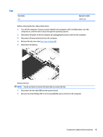
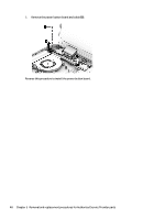
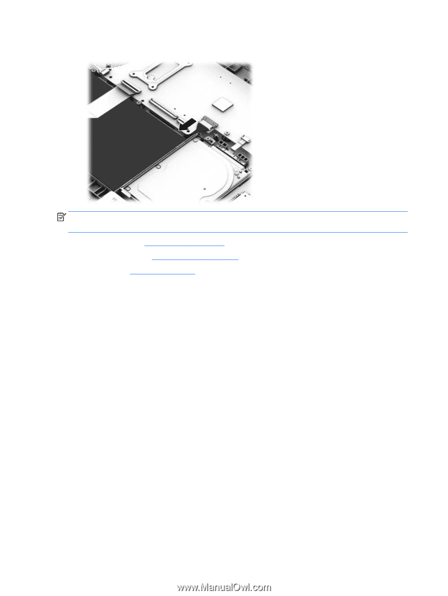
5. Disconnect the battery. NOTE: When replacing the system board, be sure that the following components are removed from the defective system board and installed on the replacement system board: ● WLAN module (see WLAN module on page 40) ● Memory module (see Memory module on page 52) ● Heat sink (see Heat sink on page 54) Remove the system board: 1. Disconnect the following cables from the system board: (1): Power button board cable (2): Left display cable (3): Power connector cable (4): Right display cable (5): Fan cable (6): USB/audio cable (7): Hard drive cable 50 Chapter 5 Removal and replacement procedures for Authorized Service Provider parts
-
 1
1 -
2
-
3
-
4
-
5
-
6
-
7
-
8
-
9
-
10
-
11
-
12
-
13
-
14
-
15
-
16
-
17
-
18
-
19
-
20
-
21
-
22
-
23
-
24
-
25
-
26
-
27
-
28
-
29
-
30
-
31
-
32
-
33
-
34
-
35
-
36
-
37
-
38
-
39
-
40
-
41
-
42
-
43
-
44
-
45
-
46
-
47
-
48
-
49
-
50
-
51
-
52
-
 53
53 -
 54
54 -
 55
55 -
 56
56 -
 57
57 -
 58
58 -
 59
59 -
 60
60 -
 61
61 -
 62
62 -
 63
63 -
64
-
65
-
66
-
67
-
68
-
69
-
70
-
71
-
72
-
73
-
74
-
75
-
76
-
77
-
78
-
79
-
80
-
81
-
82
-
83
-
84
-
85
-
86
 |
 |
5.
Disconnect the battery.
NOTE:
When replacing the system board, be sure that the following components are removed from the
defective system board and installed on the replacement system board:
●
WLAN module (see
WLAN module
on page
40
)
●
Memory module (see
Memory module
on page
52
)
●
Heat sink (see
Heat sink
on page
54
)
Remove the system board:
1.
Disconnect the following cables from the system board:
(1):
Power button board cable
(2):
Left display cable
(3):
Power connector cable
(4):
Right display cable
(5):
Fan cable
(6):
USB/audio cable
(7):
Hard drive cable
50
Chapter 5
Removal and replacement procedures for Authorized Service Provider parts