HP ENVY 15-u200 Maintenance and Service Guide - Page 59
and then pull it away from the side connectors and remove it from the computer.
 |
View all HP ENVY 15-u200 manuals
Add to My Manuals
Save this manual to your list of manuals |
Page 59 highlights
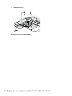
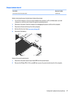
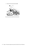
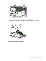
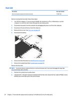
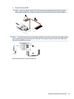
2. Remove the two nuts (1) that secure the system board to the computer. 3. Remove the five Phillips PM2.5×4.0 screws (2) that secure the system board to the computer. 4. Flex the side of the computer so you can lift the heat sink out (3), and then lift the left side of the system board (4), and then pull it away from the side connectors and remove it from the computer. 5. Reverse this procedure to install the system board. Component replacement procedures 51
-
 1
1 -
2
-
3
-
4
-
5
-
6
-
7
-
8
-
9
-
10
-
11
-
12
-
13
-
14
-
15
-
16
-
17
-
18
-
19
-
20
-
21
-
22
-
23
-
24
-
25
-
26
-
27
-
28
-
29
-
30
-
31
-
32
-
33
-
34
-
35
-
36
-
37
-
38
-
39
-
40
-
41
-
42
-
43
-
44
-
45
-
46
-
47
-
48
-
49
-
50
-
51
-
52
-
53
-
 54
54 -
 55
55 -
 56
56 -
 57
57 -
 58
58 -
 59
59 -
 60
60 -
 61
61 -
 62
62 -
 63
63 -
 64
64 -
65
-
66
-
67
-
68
-
69
-
70
-
71
-
72
-
73
-
74
-
75
-
76
-
77
-
78
-
79
-
80
-
81
-
82
-
83
-
84
-
85
-
86
 |
 |
2.
Remove the two nuts
(1)
that secure the system board to the computer.
3.
Remove the five Phillips PM2.5×4.0 screws
(2)
that secure the system board to the computer.
4.
Flex the side of the computer so you can lift the heat sink out
(3)
, and then lift the left side of the
system board
(4)
, and then pull it away from the side connectors and remove it from the computer.
5.
Reverse this procedure to install the system board.
Component replacement procedures
51