HP ENVY 17-1000 HP ENVY 17 - Maintenance and Service Guide - Page 61
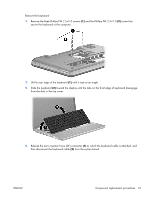
Remove the two Phillips PM2.5×5.0 screws, TouchPad cable from the system board.
 |
View all HP ENVY 17-1000 manuals
Add to My Manuals
Save this manual to your list of manuals |
Page 61 highlights
3. Remove the eight Phillips PM2.5×8.0 screws (2) that secure the top cover to the computer. 4. Remove the three Phillips PM2.5×5.0 screws (3) that secure the top cover to the computer in the battery bay. 5. Turn the computer display-side up, with the front toward you. 6. Open the computer as far as it will open. 7. Release the ZIF connector (1) to which the power button board cable is attached, and then disconnect the power button board cable from the system board. 8. Release the ZIF connector (2) to which the TouchPad cable is attached, and then disconnect the TouchPad cable from the system board. 9. Remove the two Phillips PM2.5×5.0 screws (3) that secure the top cover to computer. 10. Lift the rear edge of the top cover (1) until it rests at an angle. ENWW Component replacement procedures 53
-
 1
1 -
2
-
3
-
4
-
5
-
6
-
7
-
8
-
9
-
10
-
11
-
12
-
13
-
14
-
15
-
16
-
17
-
18
-
19
-
20
-
21
-
22
-
23
-
24
-
25
-
26
-
27
-
28
-
29
-
30
-
31
-
32
-
33
-
34
-
35
-
36
-
37
-
38
-
39
-
40
-
41
-
42
-
43
-
44
-
45
-
46
-
47
-
48
-
49
-
50
-
51
-
52
-
53
-
54
-
55
-
 56
56 -
 57
57 -
 58
58 -
 59
59 -
 60
60 -
 61
61 -
 62
62 -
 63
63 -
 64
64 -
 65
65 -
 66
66 -
67
-
68
-
69
-
70
-
71
-
72
-
73
-
74
-
75
-
76
-
77
-
78
-
79
-
80
-
81
-
82
-
83
-
84
-
85
-
86
-
87
-
88
-
89
-
90
-
91
-
92
-
93
-
94
-
95
-
96
-
97
-
98
-
99
-
100
-
101
-
102
-
103
-
104
-
105
-
106
-
107
-
108
-
109
-
110
-
111
-
112
-
113
-
114
-
115
-
116
 |
 |
