HP ENVY 17-1000 HP ENVY 17 - Maintenance and Service Guide - Page 80
from the display panel cable., Disconnect the logo light cable
 |
View all HP ENVY 17-1000 manuals
Add to My Manuals
Save this manual to your list of manuals |
Page 80 highlights
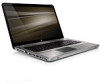
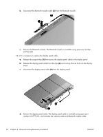
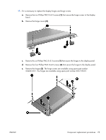
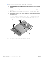
7. If it is necessary to replace the display enclosure or any of the display assembly internal components: a. Remove the Mylar screw covers (1). The screw covers are included in the Display Screw Kit, spare part number 603776-001. b. Remove the two Phillips PM2.5×5.0 screws (2) that secure the display enclosure to the display assembly. c. Lift the bottom edge of the display bezel/panel assembly (1) until it rests at a slight angle. d. Disconnect the logo light cable (2) from the display panel cable. e. Release the wireless antenna cables (3) from the right display hinge. f. Remove the display bezel/panel assembly (4). g. Set the display enclosure aside. The display enclosure is available using spare part number 603775-001. 72 Chapter 4 Removal and replacement procedures ENWW
-
 1
1 -
2
-
3
-
4
-
5
-
6
-
7
-
8
-
9
-
10
-
11
-
12
-
13
-
14
-
15
-
16
-
17
-
18
-
19
-
20
-
21
-
22
-
23
-
24
-
25
-
26
-
27
-
28
-
29
-
30
-
31
-
32
-
33
-
34
-
35
-
36
-
37
-
38
-
39
-
40
-
41
-
42
-
43
-
44
-
45
-
46
-
47
-
48
-
49
-
50
-
51
-
52
-
53
-
54
-
55
-
56
-
57
-
58
-
59
-
60
-
61
-
62
-
63
-
64
-
65
-
66
-
67
-
68
-
69
-
70
-
71
-
72
-
73
-
74
-
 75
75 -
 76
76 -
 77
77 -
 78
78 -
 79
79 -
 80
80 -
 81
81 -
 82
82 -
 83
83 -
 84
84 -
 85
85 -
86
-
87
-
88
-
89
-
90
-
91
-
92
-
93
-
94
-
95
-
96
-
97
-
98
-
99
-
100
-
101
-
102
-
103
-
104
-
105
-
106
-
107
-
108
-
109
-
110
-
111
-
112
-
113
-
114
-
115
-
116
 |
 |
