HP ENVY Rove 20-k014ca HP ENVY Rove 20 Mobile All-in-One PC - Maintenance and - Page 62
System board, Remove the fan see
 |
View all HP ENVY Rove 20-k014ca manuals
Add to My Manuals
Save this manual to your list of manuals |
Page 62 highlights
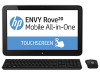
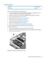
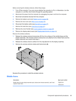
System board NOTE: The system board spare part kit includes replacement thermal material. Description System board equipped with an Intel i5-4200U 1.60-GHz processor (turbo up to 2.60-GHz; dual core, ULV, 15 W), a graphics subsystem with UMA memory, and the Windows 8 Standard operating system System board equipped with an Intel i5-4200U 1.60-GHz processor (turbo up to 2.60-GHz; dual core, ULV, 15 W), a graphics subsystem with UMA memory, and the Windows 7/Linux operating system System board equipped with an Intel i3-4010U 1.70-GHz processor (dual core, ULV, 15 W), a graphics subsystem with UMA memory, and the Windows 8 Standard operating system System board equipped with an Intel i3-4010U 1.70-GHz processor (dual core, ULV, 15 W), a graphics subsystem with UMA memory, and the Windows 7/Linux operating system Spare part number 737670-501 737670-001 728077-501 728077-001 Before removing the system board, follow these steps: 1. Turn off the computer. If you are unsure whether the computer is off or in Hibernation, turn the computer on, and then shut it down through the operating system. 2. Disconnect the power from the computer by unplugging the power cord from the computer. 3. Disconnect all external devices from the computer. 4. Remove the bottom cover (see Bottom cover on page 23). 5. Remove the rear cover (see Rear cover on page 26). 6. Disconnect the battery cable (see Hard drive on page 27). 7. Remove the hard drive (see Hard drive on page 27). 8. Remove the cover bracket (see X-axis capacitor board on page 33). 9. Remove the display stand recess (see Display stand recess on page 41). 10. Remove the fan (see Fan on page 53). When replacing the system board, be sure that the following components are removed from the defective system board and installed on the replacement system board: ● Memory module (see Memory module on page 29) ● WLAN module (see WLAN module on page 49) ● Heat sink (see Heat sink on page 56) 54 Chapter 4 Removal and replacement procedures
-
 1
1 -
2
-
3
-
4
-
5
-
6
-
7
-
8
-
9
-
10
-
11
-
12
-
13
-
14
-
15
-
16
-
17
-
18
-
19
-
20
-
21
-
22
-
23
-
24
-
25
-
26
-
27
-
28
-
29
-
30
-
31
-
32
-
33
-
34
-
35
-
36
-
37
-
38
-
39
-
40
-
41
-
42
-
43
-
44
-
45
-
46
-
47
-
48
-
49
-
50
-
51
-
52
-
53
-
54
-
55
-
56
-
 57
57 -
 58
58 -
 59
59 -
 60
60 -
 61
61 -
 62
62 -
 63
63 -
 64
64 -
 65
65 -
 66
66 -
 67
67 -
68
-
69
-
70
-
71
-
72
-
73
-
74
-
75
-
76
-
77
-
78
-
79
-
80
-
81
-
82
-
83
-
84
-
85
-
86
-
87
-
88
-
89
 |
 |
