HP ENVY Sleekbook 4-1117nr HP ENVY 4 Sleekbook HP ENVY 4 Ultrabook HP ENVY 4 U - Page 67
Remove the USB/Audio and cable see USB/Audio., USB/Audio see USB/Audio
 |
View all HP ENVY Sleekbook 4-1117nr manuals
Add to My Manuals
Save this manual to your list of manuals |
Page 67 highlights
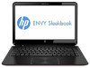
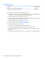
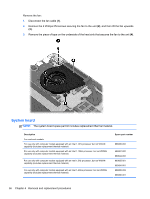
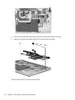
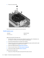
8. Remove the hard drive (see Hard drive on page 46). 9. Disconnect the display panel cable from the system board (see Display panel on page 39). 10. Remove the speaker (see Speakers on page 68). 11. Remove the power connector and cable (see Power connector cable on page 67). 12. Remove the USB/Audio and cable (see USB/Audio). When replacing the system board, be sure that the following components are removed from the defective system board and installed on the replacement system board: ● RTC battery (see RTC battery on page 49) ● Memory module (see Memory module on page 50) ● Power connector cable (see Power connector cable on page 67) ● Fan (see Heat sink on page 61) ● Heat sink (see Heat sink on page 61) ● WLAN module see (WLAN module on page 52). ● Hard drive (see Hard drive on page 46). ● USB/Audio (see USB/Audio) ● Display panel cable (see Display panel on page 39). Remove the system board: 1. Remove the following cables: ● Power connector cable (1) ● Speaker cable (2) ● Subwoofer cable (3) ● USB/Audio board cable (4) ● Keyboard cable (5) ● Keyboard light cable (6) ● TouchPad board cable (7) ● Wireless cable (8) ● Display panel cable (9) ● Power button board cable (10) Component replacement procedures 59
-
 1
1 -
2
-
3
-
4
-
5
-
6
-
7
-
8
-
9
-
10
-
11
-
12
-
13
-
14
-
15
-
16
-
17
-
18
-
19
-
20
-
21
-
22
-
23
-
24
-
25
-
26
-
27
-
28
-
29
-
30
-
31
-
32
-
33
-
34
-
35
-
36
-
37
-
38
-
39
-
40
-
41
-
42
-
43
-
44
-
45
-
46
-
47
-
48
-
49
-
50
-
51
-
52
-
53
-
54
-
55
-
56
-
57
-
58
-
59
-
60
-
61
-
 62
62 -
 63
63 -
 64
64 -
 65
65 -
 66
66 -
 67
67 -
 68
68 -
 69
69 -
 70
70 -
 71
71 -
 72
72 -
73
-
74
-
75
-
76
-
77
-
78
-
79
-
80
-
81
-
82
-
83
-
84
-
85
-
86
-
87
-
88
-
89
-
90
-
91
-
92
-
93
-
94
-
95
-
96
-
97
-
98
-
99
-
100
-
101
-
102
-
103
-
104
-
105
-
106
-
107
-
108
-
109
-
110
-
111
-
112
-
113
-
114
-
115
-
116
 |
 |