HP ENVY TouchSmart 17-j141nr HP ENVY 17 Notebook PC HP ENVY TouchSmart m7 Note - Page 88
Heat sink
 |
View all HP ENVY TouchSmart 17-j141nr manuals
Add to My Manuals
Save this manual to your list of manuals |
Page 88 highlights
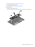
3. Lift the system board (1) , and then remove the system board (2) by sliding it up and to the right at an angle. Reverse this procedure to install the system board. Heat sink Description Spare part number For use only on computer models equipped with the Intel HM87 Express Chipset and an Nvidia 720233-001 N14P-GT (GeForce 750M) graphics subsystem For use only on computer models equipped with the Intel HM87 Express Chipset and an Nvidia 720232-001 N14P-GV2 (GeForce 740M) graphics subsystem For use only on computer models equipped with the Intel HM87 Express Chipset and a graphics 720231-001 subsystem with UMA memory NOTE: To properly ventilate the computer, allow at least 7.6 cm (3 in) of clearance on the left side of the computer. The computer uses an electric fan for ventilation. The fan is controlled by a temperature sensor and is designed to turn on automatically when high temperature conditions exist. These conditions are affected by high external temperatures, system power consumption, power management/battery conservation configurations, battery fast charging, and software requirements. Exhaust air is displaced through the ventilation grill located on the left side of the computer. Before removing the heat sink, follow these steps: 1. Shut down the computer. If you are unsure whether the computer is off or in Hibernation, turn the computer on, and then shut it down through the operating system. 2. Disconnect all external devices connected to the computer. 3. Disconnect the power from the computer by first unplugging the power cord from the AC outlet and then unplugging the AC adapter from the computer. 4. Remove the battery (see Battery on page 39), 5. Remove the display panel (see Display panel on page 50). 6. Remove the service cover (see Service cover on page 40). 78 Chapter 6 Removal and replacement procedures for Authorized Service Provider parts
-
 1
1 -
2
-
3
-
4
-
5
-
6
-
7
-
8
-
9
-
10
-
11
-
12
-
13
-
14
-
15
-
16
-
17
-
18
-
19
-
20
-
21
-
22
-
23
-
24
-
25
-
26
-
27
-
28
-
29
-
30
-
31
-
32
-
33
-
34
-
35
-
36
-
37
-
38
-
39
-
40
-
41
-
42
-
43
-
44
-
45
-
46
-
47
-
48
-
49
-
50
-
51
-
52
-
53
-
54
-
55
-
56
-
57
-
58
-
59
-
60
-
61
-
62
-
63
-
64
-
65
-
66
-
67
-
68
-
69
-
70
-
71
-
72
-
73
-
74
-
75
-
76
-
77
-
78
-
79
-
80
-
81
-
82
-
 83
83 -
 84
84 -
 85
85 -
 86
86 -
 87
87 -
 88
88 -
 89
89 -
 90
90 -
 91
91 -
 92
92 -
 93
93 -
94
-
95
-
96
-
97
-
98
-
99
-
100
-
101
-
102
-
103
-
104
-
105
-
106
-
107
-
108
-
109
-
110
-
111
-
112
-
113
-
114
-
115
-
116
 |
 |
