HP ENVY TouchSmart 17-j141nr HP ENVY 17 Notebook PC HP ENVY TouchSmart m7 Note - Page 90
Remove the RTC battery see RTC battery see
 |
View all HP ENVY TouchSmart 17-j141nr manuals
Add to My Manuals
Save this manual to your list of manuals |
Page 90 highlights
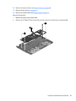
Description Intel Quad Core i7-4700MQ 2.40-GHz (SC turbo up to 3.40-GHz) processor (1600-MHz FSB, 6.0-MB L3 cache, 47 W) Intel Dual Core i5-4330M 2.80-GHz (SC turbo up to 3.50-GHz) processor (1600-MHz FSB, 3.0MB L3 cache, 37 W) Intel Dual Core i5-4200M 2.50-GHz (SC turbo up to 3.10-GHz) processor (1600-MHz FSB, 3.0MB L3 cache, 37 W) Intel Dual Core i3-4000M 2.40-GHz processor (1600-MHz FSB, 3.0-MB L3 cache, 37 W) Spare part number 723521-001 738201-001 737328-001 737327-001 Before removing the processor, follow these steps: 1. Shut down the computer. If you are unsure whether the computer is off or in Hibernation, turn the computer on, and then shut it down through the operating system. 2. Disconnect all external devices connected to the computer. 3. Disconnect the power from the computer by first unplugging the power cord from the AC outlet and then unplugging the AC adapter from the computer. 4. Remove the battery (see Battery on page 39), 5. Remove the display panel (see Display panel on page 50). 6. Remove the service cover (see Service cover on page 40). 7. Remove the hard drive (see Hard drive on page 41). 8. Remove the RTC battery (see RTC battery (see RTC battery on page 54). 9. Remove the memory modules (see Memory modules on page 43). 10. Remove the WLAN module (see WLAN module on page 44). 11. Remove the optical drive (see Optical drive on page 46). 12. Remove the base enclosure (see Base enclosure on page 55). 13. Remove the fan (see Fan on page 74). 14. Remove the system board (see System board on page 76). 15. Remove the heat sink (see Heat sink on page 78). 80 Chapter 6 Removal and replacement procedures for Authorized Service Provider parts
-
 1
1 -
2
-
3
-
4
-
5
-
6
-
7
-
8
-
9
-
10
-
11
-
12
-
13
-
14
-
15
-
16
-
17
-
18
-
19
-
20
-
21
-
22
-
23
-
24
-
25
-
26
-
27
-
28
-
29
-
30
-
31
-
32
-
33
-
34
-
35
-
36
-
37
-
38
-
39
-
40
-
41
-
42
-
43
-
44
-
45
-
46
-
47
-
48
-
49
-
50
-
51
-
52
-
53
-
54
-
55
-
56
-
57
-
58
-
59
-
60
-
61
-
62
-
63
-
64
-
65
-
66
-
67
-
68
-
69
-
70
-
71
-
72
-
73
-
74
-
75
-
76
-
77
-
78
-
79
-
80
-
81
-
82
-
83
-
84
-
 85
85 -
 86
86 -
 87
87 -
 88
88 -
 89
89 -
 90
90 -
 91
91 -
 92
92 -
 93
93 -
 94
94 -
 95
95 -
96
-
97
-
98
-
99
-
100
-
101
-
102
-
103
-
104
-
105
-
106
-
107
-
108
-
109
-
110
-
111
-
112
-
113
-
114
-
115
-
116
 |
 |
