HP ENVY TouchSmart m6-k054ca HP ENVY m6 Sleekbook HP ENVY Touchsmart m6 SleekB - Page 59
These screws must be installed in the sequence that is marked on the heat sink so that
 |
View all HP ENVY TouchSmart m6-k054ca manuals
Add to My Manuals
Save this manual to your list of manuals |
Page 59 highlights
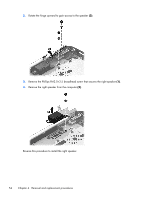
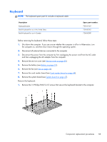
2. Remove the heat sink (2) from the system board. 3. Note the locations of thermal material over the soldered on processor on the system board (1) and the bottom of the heat sink that services it (2). Reverse this procedure to install the heat sink. CAUTION: These screws must be installed in the sequence that is marked on the heat sink so that the correct pressure is applied to the processor and other components. Component replacement procedures 51
-
 1
1 -
2
-
3
-
4
-
5
-
6
-
7
-
8
-
9
-
10
-
11
-
12
-
13
-
14
-
15
-
16
-
17
-
18
-
19
-
20
-
21
-
22
-
23
-
24
-
25
-
26
-
27
-
28
-
29
-
30
-
31
-
32
-
33
-
34
-
35
-
36
-
37
-
38
-
39
-
40
-
41
-
42
-
43
-
44
-
45
-
46
-
47
-
48
-
49
-
50
-
51
-
52
-
53
-
 54
54 -
 55
55 -
 56
56 -
 57
57 -
 58
58 -
 59
59 -
 60
60 -
 61
61 -
 62
62 -
 63
63 -
 64
64 -
65
-
66
-
67
-
68
-
69
-
70
-
71
-
72
-
73
-
74
-
75
-
76
-
77
-
78
-
79
-
80
-
81
-
82
-
83
-
84
-
85
-
86
-
87
-
88
-
89
-
90
-
91
-
92
-
93
-
94
-
95
-
96
 |
 |

2.
Remove the heat sink
(2)
from the system board.
3.
Note the locations of thermal material over the soldered on processor on the system board
(1)
and the bottom of the heat sink that services it
(2)
.
Reverse this procedure to install the heat sink.
CAUTION:
These screws must be installed in the sequence that is marked on the heat sink so that the
correct pressure is applied to the processor and other components.
Component replacement procedures
51