HP ENVY m7-u100 Maintenance and Service Guide - Page 53
to the keyboard/top cover., that secure the plastic support bridges and the heat sink
 |
View all HP ENVY m7-u100 manuals
Add to My Manuals
Save this manual to your list of manuals |
Page 53 highlights
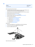
2. Remove the three Phillips M2.0×4.8 screws (1) that secure the power connector cable bracket to the keyboard/top cover. 3. Remove the power connector cable bracket (2). 4. Remove the two Phillips M2.0×3.8 screws (3) that secure the system board to the keyboard/top cover. 5. Remove the four Phillips M2.0×4.8 screws (4) that secure the plastic support bridges and the heat sink to the keyboard/top cover. 6. Remove the plastic support bridges (5). The plastic support bridges are included in the I/O Bracket Kit, spare part number 857824-001. 7. Release the system board (1) by lifting the right side and swinging it up and to the left until it rests at an angle. Component replacement procedures 45
-
 1
1 -
2
-
3
-
4
-
5
-
6
-
7
-
8
-
9
-
10
-
11
-
12
-
13
-
14
-
15
-
16
-
17
-
18
-
19
-
20
-
21
-
22
-
23
-
24
-
25
-
26
-
27
-
28
-
29
-
30
-
31
-
32
-
33
-
34
-
35
-
36
-
37
-
38
-
39
-
40
-
41
-
42
-
43
-
44
-
45
-
46
-
47
-
 48
48 -
 49
49 -
 50
50 -
 51
51 -
 52
52 -
 53
53 -
 54
54 -
 55
55 -
 56
56 -
 57
57 -
 58
58 -
59
-
60
-
61
-
62
-
63
-
64
-
65
-
66
-
67
-
68
-
69
-
70
-
71
-
72
-
73
-
74
-
75
-
76
-
77
-
78
 |
 |

2.
Remove the three Phillips M2.0×4.8 screws
(1)
that secure the power connector cable bracket to
the keyboard/top cover.
3.
Remove the power connector cable bracket
(2)
.
4.
Remove the two Phillips M2.0×3.8 screws
(3)
that secure the system board to the keyboard/top cover.
5.
Remove the four Phillips M2.0×4.8 screws
(4)
that secure the plastic support bridges and the heat sink
to the keyboard/top cover.
6.
Remove the plastic support bridges
(5)
.
The plastic support bridges are included in the I/O Bracket Kit, spare part number 857824-001.
7.
Release the system board
(1)
by lifting the right side and swinging it up and to the left until it rests at
an angle.
Component replacement procedures
45