HP ENVY m7-u100 Maintenance and Service Guide - Page 59
Display assembly
 |
View all HP ENVY m7-u100 manuals
Add to My Manuals
Save this manual to your list of manuals |
Page 59 highlights
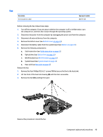
Reverse this procedure to install the speakers. Display assembly Description Spare part number Display assemblies for use only on computer models with model numbers 17-u100 through 17-u199: 17.3-in, UHD, WLED, AntiGlare (3840×2160), flat-flat (4.0-mm), UWVA, eDP+PSR, touch screen display assembly equipped with HDC and webcam 857436-001 17.3-in, FHD, WLED, AntiGlare (1920×1080), flat-flat (4.0-mm), UWVA, eDP, touch screen display assembly equipped with HDC and webcam 857435-001 17.3-in, UHD, WLED, AntiGlare (3840×2160), flat-flat (4.0-mm), UWVA, eDP+PSR non-touch scree, display assembly equipped with HDC and webcam 933257-001 17.3-in, FHD, WLED, AntiGlare (1920×1080), flat-flat (4.0-mm), UWVA, eDP non-touch screen display assembly equipped with HDC and webcam 933256-001 Display assemblies for use on all computer models: 17.3-in, UHD, WLED, AntiGlare (3840×2160), uslim-flat (2.68-mm), UWVA, eDP+PSR TouchScreen display assembly equipped with f3DC and webcam 859440-001 17.3-in, FHD, WLED, BrightView (1920×1080), slim-flat (3.0-mm), UWVA, eDP TouchScreen display assembly equipped with f3DC and webcam 859439-001 Display assemblies for use only on computer models with model numbers 17-u200 through 17-u299: 17.3-in, UHD, WLED, eDP+PSR, AntiGlare (3840×2160), flat-flat (4.0-mm), UWVA, TouchScreen display assembly equipped with HDC and IR webcam 926687-001 17.3-in, FHD, WLED, eDP, AntiGlare (1920×1080), flat-flat (4.0-mm), UWVA, eDP TouchScreen display assembly equipped with HDC and IR webcam 926686-001 17.3-in, UHD, WLED, AntiGlare (3840×2160), flat-flat (4.0-mm), UWVA, eDP+PSR non-touch scree, display assembly equipped with HDC and webcam 933259-001 17.3-in, FHD, WLED, AntiGlare (1920×1080), flat-flat (4.0-mm), UWVA, eDP non-touch screen display assembly equipped with HDC and webcam 933258-001 Before removing the display assembly, follow these steps: 1. Turn off the computer. If you are unsure whether the computer is off or in Hibernation, turn the computer on, and then shut it down through the operating system. 2. Disconnect the power from the computer by unplugging the power cord from the computer. 3. Disconnect all external devices from the computer. 4. Remove the bottom cover (see Bottom cover on page 24). 5. Disconnect the battery cable from the system board (see Battery on page 26). Remove the display assembly: 1. Release the ZIF connector (1) to which the display panel cable is connected, and then disconnect the display panel cable from the system board. 2. Release the ZIF connector (2) to which the webcam/microphone module cable is connected, and then disconnect the webcam/microphone module cable from the system board. Component replacement procedures 51
-
 1
1 -
2
-
3
-
4
-
5
-
6
-
7
-
8
-
9
-
10
-
11
-
12
-
13
-
14
-
15
-
16
-
17
-
18
-
19
-
20
-
21
-
22
-
23
-
24
-
25
-
26
-
27
-
28
-
29
-
30
-
31
-
32
-
33
-
34
-
35
-
36
-
37
-
38
-
39
-
40
-
41
-
42
-
43
-
44
-
45
-
46
-
47
-
48
-
49
-
50
-
51
-
52
-
53
-
 54
54 -
 55
55 -
 56
56 -
 57
57 -
 58
58 -
 59
59 -
 60
60 -
 61
61 -
 62
62 -
 63
63 -
 64
64 -
65
-
66
-
67
-
68
-
69
-
70
-
71
-
72
-
73
-
74
-
75
-
76
-
77
-
78
 |
 |
