HP HDX X16-1001XX HP HDX 16 Entertainment PC - Maintenance and Service Guide - Page 96
Processor
 |
View all HP HDX X16-1001XX manuals
Add to My Manuals
Save this manual to your list of manuals |
Page 96 highlights
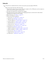
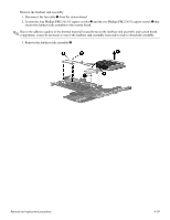
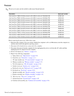
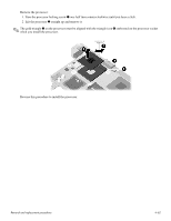
Processor ✎ The processor spare part kit includes replacement thermal material. Description Intel Core2 Duo T9800 2.93-GHz processor with 6-MB L2 cache and 1066-MHz FSB Intel Core2 Duo T9600 2.80-GHz processor with 6-MB L2 cache and 1066-MHz FSB Intel Core2 Duo T9550 2.66-GHz processor with 6-MB L2 cache and 1066-MHz FSB Intel Core2 Duo T9500 2.53-GHz processor with 6-MB L2 cache and 1066-MHz FSB Intel Core2 Duo T8700 2.53-GHz processor with 3-MB L2 cache and 1066-MHz FSB Intel Core2 Duo T8600 2.40-GHz processor with 3-MB L2 cache and 1066-MHz FSB Intel Core2 Duo T8400 2.26-GHz processor with 3-MB L2 cache and 1066-MHz FSB Intel Core2 Duo T6600 2.20-GHz processor with 3-MB L2 cache and 1066-MHz FSB Intel Core2 Duo T7550 2.13-GHz processor with 3-MB L2 cache and 1066-MHz FSB Intel Core2 Duo T6400 2.06-GHz processor with 3-MB L2 cache and 1066-MHz FSB Intel Core2 Duo T7350 2.00-GHz processor with 3-MB L2 cache and 1066-MHz FSB Spare part number 507951-001 500604-001 507953-001 500603-001 507960-001 500601-001 500600-001 513591-001 500605-001 513593-001 503392-001 Before removing the processor, follow these steps: 1. Shut down the computer. If you are unsure whether the computer is off or in Hibernation, turn the computer on, and then shut it down through the operating system. 2. Disconnect all external devices connected to the computer. 3. Disconnect the power from the computer by first unplugging the power cord from the AC outlet and then unplugging the AC adapter from the computer. 4. Remove the battery (see "Battery" on page 4-8). 5. Remove the following components: a. Optical drive (see "Optical drive" on page 4-9) b. Hard drive (see "Hard drive" on page 4-11) c. TV tuner module (see "TV tuner module" on page 4-13) d. Memory module (see "Memory module" on page 4-15) e. WLAN module (see "WLAN module" on page 4-16) f. Switch cover (see "Switch cover" on page 4-18) g. Keyboard cover (see "Keyboard cover" on page 4-20) h. Keyboard (see "Keyboard" on page 4-24) i. Speaker assembly (see "Speaker assembly" on page 4-30) j. Display assembly (see "Display assembly" on page 4-31) k. Top cover (see "Top cover" on page 4-39) l. System board (see "System board" on page 4-45) m. Fan/heat sink assembly (see "Fan/heat sink assembly" on page 4-58) Removal and replacement procedures 4-61
-
 1
1 -
2
-
3
-
4
-
5
-
6
-
7
-
8
-
9
-
10
-
11
-
12
-
13
-
14
-
15
-
16
-
17
-
18
-
19
-
20
-
21
-
22
-
23
-
24
-
25
-
26
-
27
-
28
-
29
-
30
-
31
-
32
-
33
-
34
-
35
-
36
-
37
-
38
-
39
-
40
-
41
-
42
-
43
-
44
-
45
-
46
-
47
-
48
-
49
-
50
-
51
-
52
-
53
-
54
-
55
-
56
-
57
-
58
-
59
-
60
-
61
-
62
-
63
-
64
-
65
-
66
-
67
-
68
-
69
-
70
-
71
-
72
-
73
-
74
-
75
-
76
-
77
-
78
-
79
-
80
-
81
-
82
-
83
-
84
-
85
-
86
-
87
-
88
-
89
-
90
-
 91
91 -
 92
92 -
 93
93 -
 94
94 -
 95
95 -
 96
96 -
 97
97 -
 98
98 -
 99
99 -
 100
100 -
 101
101 -
102
-
103
-
104
-
105
-
106
-
107
-
108
-
109
-
110
-
111
-
112
-
113
-
114
-
115
-
116
-
117
-
118
-
119
-
120
-
121
-
122
-
123
-
124
-
125
-
126
-
127
-
128
-
129
-
130
-
131
-
132
-
133
-
134
-
135
-
136
-
137
-
138
-
139
-
140
-
141
-
142
-
143
-
144
-
145
-
146
 |
 |
