HP HDX X16-1012TX HP HDX 16 Entertainment PC - Maintenance and Service Guide - Page 69
from the display enclosure., Detach the transceivers
 |
View all HP HDX X16-1012TX manuals
Add to My Manuals
Save this manual to your list of manuals |
Page 69 highlights
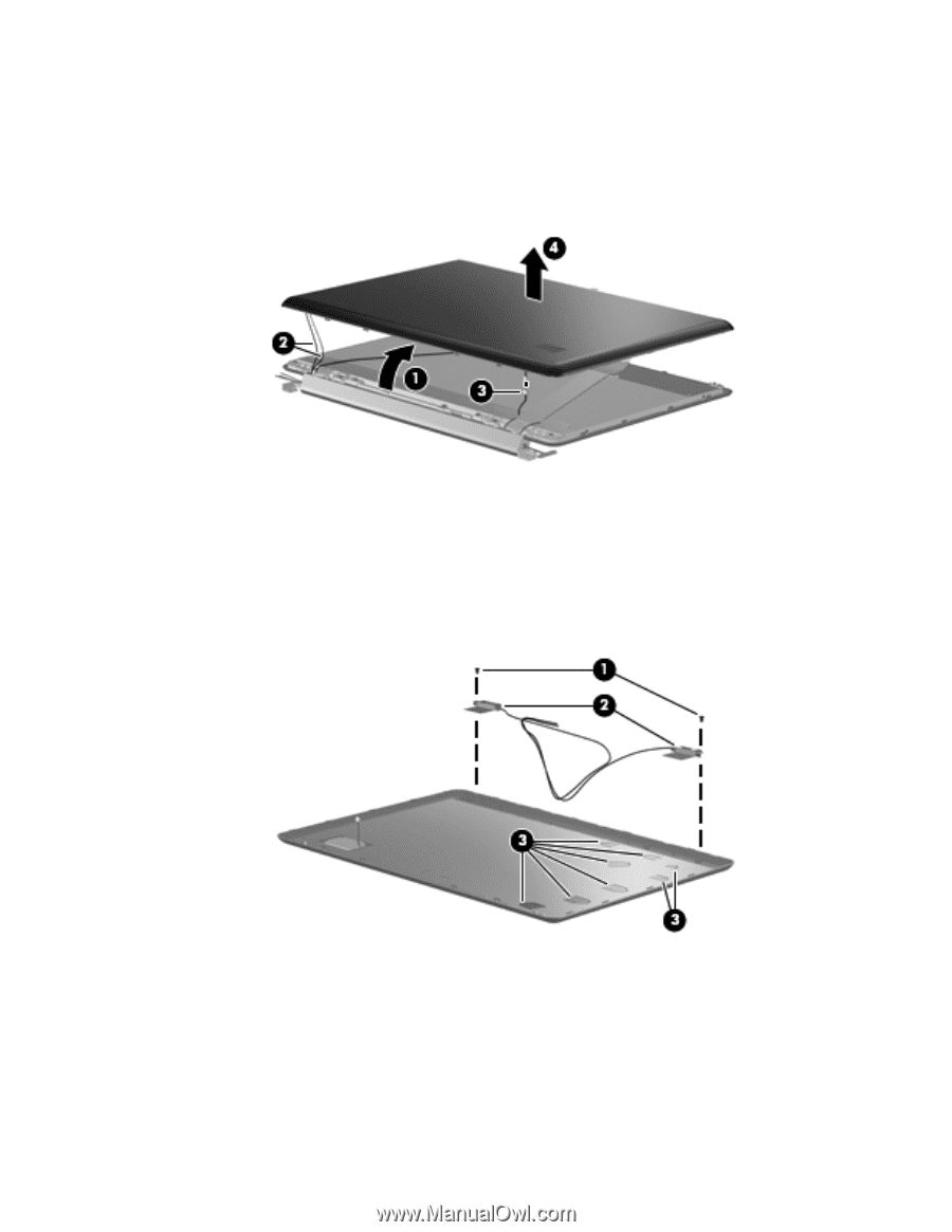
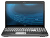
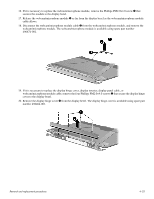
8. Turn the display assembly upside down, with the bottom edge toward you. 9. Release the display enclosure bottom edge 1 as far as the wireless antenna cables and display logo LED cable allow. 10. Remove the wireless antenna cables 2 from the slot built into the display hinge cover. 11. Disconnect the display logo LED cable 3 from the display logo LED board. 12. Remove the display enclosure 4. The display enclosure is available using spare part number 496462-001. 13. If it is necessary to replace the wireless antenna transceivers and cables, remove the Phillips PM2.0×4.0 screw 1 that secures each transceiver to the display enclosure. 14. Detach the transceivers 2 from the display enclosure. 15. Release the retention tabs 3 built into the display enclosure and remove the wireless antenna cables from the tabs. The wireless antenna transceivers and cables are included in the Display Cable Kits, spare part numbers 496465-001 (for use only with dual-lamp display assemblies) and 514289-001 (for use only with single-lamp display assemblies). Removal and replacement procedures 4-34
-
 1
1 -
2
-
3
-
4
-
5
-
6
-
7
-
8
-
9
-
10
-
11
-
12
-
13
-
14
-
15
-
16
-
17
-
18
-
19
-
20
-
21
-
22
-
23
-
24
-
25
-
26
-
27
-
28
-
29
-
30
-
31
-
32
-
33
-
34
-
35
-
36
-
37
-
38
-
39
-
40
-
41
-
42
-
43
-
44
-
45
-
46
-
47
-
48
-
49
-
50
-
51
-
52
-
53
-
54
-
55
-
56
-
57
-
58
-
59
-
60
-
61
-
62
-
63
-
 64
64 -
 65
65 -
 66
66 -
 67
67 -
 68
68 -
 69
69 -
 70
70 -
 71
71 -
 72
72 -
 73
73 -
 74
74 -
75
-
76
-
77
-
78
-
79
-
80
-
81
-
82
-
83
-
84
-
85
-
86
-
87
-
88
-
89
-
90
-
91
-
92
-
93
-
94
-
95
-
96
-
97
-
98
-
99
-
100
-
101
-
102
-
103
-
104
-
105
-
106
-
107
-
108
-
109
-
110
-
111
-
112
-
113
-
114
-
115
-
116
-
117
-
118
-
119
-
120
-
121
-
122
-
123
-
124
-
125
-
126
-
127
-
128
-
129
-
130
-
131
-
132
-
133
-
134
-
135
-
136
-
137
-
138
-
139
-
140
-
141
-
142
-
143
-
144
-
145
-
146
 |
 |