HP Indigo 7500 Electrometer Board Test - Page 10
Use a DC Voltmeter Fluke to verify a 24V twenty four in pins 1 and 3 of the electrometer board Molex
 |
View all HP Indigo 7500 manuals
Add to My Manuals
Save this manual to your list of manuals |
Page 10 highlights
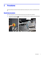
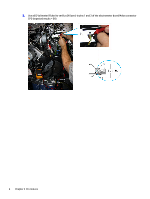
8. Set the electrometer board power to ON by typing [-1] in the Set field and press Set to activate it. 9. Use a DC Voltmeter (Fluke) to verify a 24V (twenty four) in pins 1 and 3 of the electrometer board Molex connector CP2 (expected results = 24V ±1). 10. Verify '0' Volts at the probe monitor as follows: ■ Use a DC Voltmeter (Fluke) to verify a 0V (zero) in pins 2 and 4 of the electrometer board Molex connector CP2. (Accepted results: 0.000VDC ±0.10VDC). 8 Chapter 2 Procedures
-
 1
1 -
2
-
3
-
4
-
 5
5 -
 6
6 -
 7
7 -
 8
8 -
 9
9 -
 10
10 -
 11
11 -
 12
12 -
 13
13 -
 14
14 -
 15
15 -
16
-
17
-
18
-
19
-
20
-
21
-
22
-
23
-
24
-
25
-
26
-
27
-
28
-
29
-
30
-
31
 |
 |

8.
Set the electrometer board power to
ON
by typing [-1] in the
Set
field and press
Set
to activate it.
9.
Use a DC Voltmeter (Fluke) to verify a 24V (twenty four) in pins 1 and 3 of the electrometer board Molex
connector CP2 (expected results = 24V ±1).
10.
Verify ‘0’ Volts at the probe monitor as follows:
■
Use a DC Voltmeter (Fluke) to verify a 0V (zero) in pins 2 and 4 of the electrometer board Molex
connector CP2.
(Accepted results: 0.000VDC ±0.10VDC).
8
Chapter 2
Procedures